
Introduction
A 380 kV overhead transmission line (OHTL) is a critical component of a high-voltage power transmission network. It is designed to transfer large amounts of electrical power over long distances while maintaining system reliability, voltage stability, and acceptable transmission losses.
At 380 kV, electricity can be transmitted efficiently over long distances because increasing the transmission voltage reduces current for a given power transfer. Lower current helps reduce resistive losses and allows the transmission system to transport large quantities of electrical energy efficiently.
However, constructing a 380 kV transmission line is far more than simply erecting steel towers and installing conductors. It is a carefully controlled engineering process involving:
- Route and right-of-way planning
- Structure spotting
- Access road preparation
- Foundation construction
- Tower assembly and erection
- Grounding
- Insulator installation
- Conductor stringing and sagging
- OPGW installation and splicing
- Line accessories
- Pre-commissioning inspection and electrical testing
The quality of every stage directly affects the safety, reliability, and service life of the completed transmission line.
1. Why 380 kV Transmission?
High-voltage transmission is used to transport electrical power efficiently over long distances.
The major advantages of a 380 kV transmission system include:
1.1 Reduced Transmission Losses
For a given power transfer, increasing voltage reduces the current required. Since conductor losses are proportional to the square of current, higher-voltage transmission helps reduce resistive losses.
1.2 Improved Voltage Performance
A high-voltage transmission network helps maintain appropriate voltage levels across the grid and supports stable power delivery.
1.3 Efficient Long-Distance Transmission
380 kV lines are particularly suitable for transporting large quantities of electrical energy across long distances with comparatively low energy dissipation.
1.4 Optimized Conductor Requirements
Higher transmission voltage can allow the system to transport substantial power without requiring excessively large individual conductors, subject to the complete electrical and mechanical design.
2. Main Components of a 380 kV OHTL
A typical overhead transmission line consists of several major systems.
The principal components include:
- Transmission towers
- Phase conductors
- Insulators
- Line hardware and fittings
- Grounding system
- OPGW
- Vibration control equipment
- Warning and identification systems
The uploaded construction material identifies towers, conductors, insulators, and hardware fittings/accessories as the principal OHTL components.
Each component has a specific electrical, mechanical, or safety function.
3. Types of 380 kV Transmission Towers
Transmission towers are selected according to the line geometry, deviation angle, mechanical loading, and functional requirements.
The material identifies the following tower categories:
Tangent Tower
Used for relatively straight sections of the transmission line. The referenced tower type has a deviation angle of approximately 0° to 2°.
Small Angle Tower
Used where the line changes direction by approximately 2° to 10°.
Medium Angle Tower
Used for deviation angles of approximately 10° to 35°.
Large Angle Tower
Used for deviation angles of approximately 35° to 60°.
Heavy Angle Tower
Used for major deviations from approximately 60° to 90°.
Anchor Tower
Used as a tension/anchoring structure and identified in the material with a deviation angle range of approximately 0° to 3°.
Dead-End/Terminal Tower
Used at terminal locations and other locations where the conductors require termination.
Transposition Tower
Used where conductor phase positions are changed according to the transmission-line design.
The tower selection is therefore not arbitrary. It must correspond to the approved line design and structural requirements.
4. OHTL Material Requirements
A 380 kV project involves a large number of materials and accessories.
The material list includes:
- Concrete and concrete bonding agents
- Reinforcement steel
- Backfill material
- Latticed steel structures
- Grounding materials
- Insulators
- Phase conductors
- Line hardware
- Spacer dampers and vibration dampers
- OPGW
- OPGW joint boxes
- Structure identification and danger signs
- Anti-climbing guards
- Obstruction markers and conductor lighting
- Precast concrete barriers
Proper material control is essential because material quality, identification, storage, transportation, and installation all influence the final line performance.
5. Overall 380 kV OHTL Construction Sequence
A typical construction sequence can be summarized as:
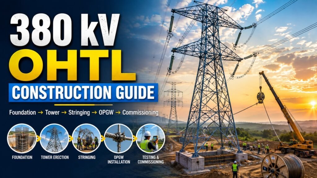
Route Survey → ROW → Structure Spotting → Access Roads → Foundation Works → Tower Assembly → Tower Erection → Grounding → Tower Accessories → Insulator Installation → Conductor Stringing → Sagging → Dead Ending & Clipping → Spacer/Damper Installation → Jumper Installation → OPGW Installation → Splicing → Testing & Commissioning
This sequence is important because subsequent activities depend on the successful completion and inspection of earlier activities.
6. Route Survey
The route survey is one of the first major engineering activities.
The objective is to identify an appropriate transmission corridor while minimizing environmental and construction impacts.
Survey activities include:
- Establishing route coordinates
- Preparing plan and profile drawings
- Identifying structure locations
- Reviewing terrain conditions
- Identifying crossings and obstacles
- Evaluating possible rerouting requirements
Where rerouting is required, field surveys are performed and revised route plans and plan/profile drawings are prepared for review and approval.
A good route reduces construction difficulties, minimizes unnecessary deviations, improves accessibility, and helps control project cost.
7. Right-of-Way (ROW)
The Right-of-Way is the strip of land required to construct, operate, maintain, and repair the transmission line.
The line is normally centered within the ROW.
The uploaded material emphasizes that the ROW should be secured before design and construction activities proceed.
For the referenced 380 kV configurations, the material indicates:
- Normal ROW width for a single transmission line: approximately 50 m
- Normal ROW width for parallel transmission lines: approximately 85 m
- Line center-to-center spacing for the referenced parallel configuration: approximately 37 m
The material also provides specific horizontal clearance values from certain existing facilities and objects. These values should always be applied together with the governing project specifications and applicable statutory requirements.
8. Structure Spotting
Structure spotting determines the exact locations where transmission towers will be installed.
The uploaded material states that structure spotting is performed using the PLS-CADD computer optimization method.
The resulting plan and profile information is summarized in the structure list.
However, computer optimization is not a substitute for field verification.
Potential problem areas must be checked, including:
- Wetlands
- Rock
- Rough terrain
- Existing power lines
- Crossings
- Other physical obstacles
This combination of engineering software and field verification is essential for developing practical tower locations.
9. Transmission Line Access Roads
Construction equipment requires safe access to every tower location.
The referenced project requirements include:
- Design speed: 48 km/h
- Minimum unpaved access-road width: 5 m
- Minimum horizontal distance from transmission-line centerline to the nearest road edge: 15 m
The typical road structure consists of:
Subgrade → Subbase → Surface/Base Course
Approximately 200 mm of topsoil is removed from the subgrade in the referenced requirements. The surface/base course is specified as approximately 300 ± 20 mm thick, with compacted layer thickness generally not exceeding 150 mm. Seawater is not to be used for compaction.
10. Foundation Construction
The foundation transfers the tower loads safely into the ground.
Foundation construction generally includes:
- Structure pad preparation
- Excavation
- Reinforcement cage installation
- Stub angle installation
- Grounding installation
- Formwork
- Concrete placement
- Concrete curing
- Backfilling and finishing
The foundation type depends on ground conditions and the approved foundation design.
The material identifies:
- Pad & Chimney Foundation
- Auger Foundation
- Anchor Foundation
- Pile Foundation
- Grillage Foundation
Different foundation types are associated with different soil conditions.
11. Structure Pad
The structure pad provides a stable working area around the tower foundation.
The referenced requirements specify that:
- The top elevation of concrete footings should not be less than 450 mm above finished structure-pad grade.
- A minimum distance of 15 m should be maintained from any point of the foundation to the top edge of the structure pad.
- The structure pad should be graded with a slope of approximately 1.5% to 2% to drain water away from the foundations.
These requirements help provide proper drainage and a suitable working platform for construction and future maintenance.
12. Reinforcement Cage Installation
The reinforcement cage must be fabricated according to approved construction drawings.
It may be assembled either at the storage yard or at the construction site.
The cage must:
- Match the approved dimensions
- Be properly supported
- Maintain the specified position
- Be protected from displacement during concreting
The material specifies the use of concrete blocks and wire tying at approximately 75–100 mm intervals on the outside of the cage.
The top of the reinforcement cage is also subject to specified positional tolerances. The referenced requirements limit horizontal deviation of the cage center and specify elevation tolerances.
13. Stub Angle Setting
Stub angles form the interface between the foundation and the steel tower.
They must be installed according to the approved drawings using a rigid setting template.
Stub setting is one of the most critical foundation activities because incorrect positioning can affect:
- Tower geometry
- Leg spacing
- Tower orientation
- Verticality
- Tower erection
- Structural loading
The material specifically identifies maintaining tower geometry and verticality, ensuring correct leg spacing/orientation, and preventing structural stress as key purposes of accurate stub setting.
14. Tower Foundation Grounding
The grounding system provides a low-impedance path for fault currents, lightning-related currents, induced surges, and static discharges.
The referenced system includes bonding the reinforcement cage to the stub angle and grounding two opposite tower legs through counterpoise conductors and copper-clad steel ground rods.
Grounding performance is particularly important for high-voltage transmission lines because inadequate grounding can increase tower potential rise and negatively affect line performance during faults and lightning events.
15. Concrete Placement and Curing
Concrete should only be placed after the formwork, reinforcement, embedded components, foundation surfaces, and relevant joints have been inspected and approved.
The material highlights several important controls:
- Concrete temperature monitoring
- Proper form-release agent
- Scheduling concrete placement during cooler periods in hot weather
- Avoiding placement during wind-blown sand conditions
- Continuous concrete supply
- Limiting free fall of fresh concrete to 1.5 m
- Avoiding placement where standing water exists
- Proper use of concrete vibrators
Concrete Curing
Curing is essential because it directly affects concrete strength, durability, and long-term foundation performance.
The referenced method uses wet burlap with continuous moisture maintenance, and exposed surfaces are specified to be cured for at least seven days.
16. Tower Ground Assembly
Once the foundation is ready, tower components are assembled.
Tower steel should be stored on suitable blocking to prevent contact with dirt, mud, and other contaminants that could damage the coating.
Assembly must follow the approved erection and detailed drawings.
Typical tower components include:
- Leg extensions
- Basic/common body
- Body extensions
- Crossarms
- Cages
- Ground-wire peaks
Damaged, bent, or twisted members should be replaced rather than installed.
17. Tower Erection
Tower erection should begin only when the foundation has achieved the required strength.
The referenced requirements state that concrete should achieve at least 75% of specified compressive strength and that erection should not begin before ten days after foundation concrete placement.
Cranes must be selected according to:
- Tower height
- Section weight
- Required lifting capacity
- Boom configuration
- Working radius
- Ground conditions
The crane should be positioned safely, with outriggers fully extended on suitable compacted ground or a designated structure pad. The referenced procedure also requires the crane to be adequately grounded.
18. Tower Bolt Tightening
Bolted connections are critical to the mechanical integrity of the tower.
The referenced requirements include:
- Minimum bolt diameter: 16 mm
- Preferred bolt diameters: 16 mm and 20 mm
- Bolt projection beyond the locknut: 3–8 mm, with at least three effective threads
- Hole diameter: 1.5 mm greater than nominal bolt diameter
- Controlled tightening using calibrated torque wrenches
Recommended torque values in the material are:
| Bolt Diameter | Recommended Torque |
|---|---|
| 16 mm | 110–135 Nm |
| 20 mm | 185–220 Nm |
Final tightening is carried out progressively from the top toward the bottom.
19. Tower Grounding and Footing Resistance
The tower grounding system is designed to provide a reliable path to earth.
The referenced grounding arrangement uses counterpoise conductors and ground rods connected to diagonally opposite tower legs.
The material describes typical ground rods as approximately 3 m long and copper-clad, with installation at least 8 m from the tower footing. The counterpoise is buried approximately 500 mm below finished grade in normal conditions.
For the referenced 380 kV system, the material gives the following structure grounding resistance criteria:
- Within 3 km of a substation: ≤ 3 ohms
- More than 3 km from a substation: ≤ 10 ohms
- Special criteria are indicated for rock soil conditions
These values should be treated as project-specific requirements and verified against the governing utility specification before application to another project.
20. Tower Identification and Safety Accessories
After tower erection, various identification and safety accessories are installed.
These include:
- Tower identification tags
- Phase identification plates
- Danger signs
- Obstruction markers
- Warning lights
- Anti-climbing guards
The referenced material specifies installation of tower tags and phase identification plates on the transverse face of the tower and provides specific requirements for danger-plate material and fixing.
21. Obstruction Markers and Warning Lights
Transmission lines located near aviation facilities or other critical areas may require visual obstruction marking.
The material specifies aviation-orange spherical markers on shield wires.
The referenced spacing is:
- Normally not more than 61 m
- Approximately 10–15 m in critical areas near airport runway ends
The material also specifies vibration-damping provisions associated with the markers.
Night warning lights are also specified on the highest-level phase conductors near structures, with vibration-damping arrangements. Tower beacons are mounted at the top and, where necessary, intermediate levels so that they remain visible from all directions.
22. Anti-Climbing Protection
Transmission towers must be protected against unauthorized climbing.
The referenced arrangement installs an anti-climbing guard approximately 4 m above finished ground level.
The gate is designed to open upward and is mounted to the tower leg using step bolts. Barbed-wire requirements depend on the tower type and height.
23. Conductor Stringing
Conductor stringing is one of the most technically sensitive stages of OHTL construction.
Before stringing begins, the construction team should prepare a detailed stringing plan covering:
- Stringing section
- Drum arrangement
- Required manpower
- Puller and tensioner locations
- Crossing arrangements
- Equipment
- Safety controls
- Communication
- Temporary grounding
The material emphasizes proper drum planning to minimize mid-span joints and short conductor pieces.
24. Insulator Installation
Insulators must be transported and stored carefully.
Important controls include:
- Keep insulators in their original shipping/storage crates until required.
- Do not place them directly on the ground.
- Verify type numbers against assembly drawings.
- Confirm correct orientation.
- Check metal fittings and hardware.
- Verify split pins, cotter pins, W-clips, nuts, and bolts.
- Ensure corona rings and arcing horns are correctly installed.
Workers should never step, sit, or crawl on insulators. Lifting lines should be attached to the insulator caps rather than the sheds or sheath.
25. Tension Stringing Method
The tension stringing method keeps the conductor under controlled tension during installation.
Its principal advantage is maintaining the conductor clear of:
- Ground
- Energized circuits
- Roads
- Structures
- Other obstacles
The process generally begins by paying out a pilot wire through travelers installed on the tower crossarms. The pilot wire is then used to pull the conductor through the stringing system using pullers and tensioners.
26. Conductor Paying Out
Pilot wires are connected to the bundled conductors using suitable running-board and swivel arrangements.
The referenced procedure recommends maintaining a paying-out speed of approximately 3–4 km/h for smooth passage through the travelers.
When only a few rounds of conductor remain on a drum, the operation is stopped and the remaining conductor is unwound before replacing the empty drum.
All pulling and tensioning equipment must be properly bonded and grounded.
Running grounds should be installed close to the tensioning setup to continuously ground the sub-conductors and overhead ground wire.
27. Rough Sagging
Rough sagging is the preliminary positioning of the conductor between towers.
Its purpose is to establish an approximate sag before final sagging and clamping.
The conductor is tensioned using the tensioner and the approximate sag is checked using sighting equipment.
An important requirement in the referenced procedure is that a rough-sagged conductor should not remain in the stringing blocks for more than 96 hours before being pulled to the specified sag.
28. Final Conductor Sagging
Final sagging is critical because the conductor must achieve the specified mechanical position.
The sag span is selected based on the equivalent span or the longest span in the stringing section.
The material identifies two principal sag measurement methods:
- Sag scope and target method
- Dynamometer method
Before sagging, the team should have:
- Approved sag tables
- Conductor temperature measurement equipment
- Sagging tools
- Identified regulating/sag-sighting spans
- Temporary grounding
- Temporary back guys
Why Accurate Sag Matters
Incorrect sag can result in:
- Insufficient ground clearance
- Excessive mechanical tension
- Clearance violations
- Unequal phase geometry
- Increased conductor stress
- Potential long-term reliability problems
Therefore, sagging must be performed according to approved sag-tension data and the applicable project requirements.
29. Dead Ending and Clipping
After the conductor reaches the specified sag, the conductor is marked and excess length is removed.
The compression dead-end is then installed, and the tension insulator assembly is connected to the crossarm.
After final sagging, the conductor is transferred from the rollers into suspension clamps.
Armor rods are installed after clipping is completed.
The material also specifies that conductors should be clamped within 96 hours of final sagging.
30. Spacer Dampers and Vibration Dampers
Bundled conductors require appropriate spacing and vibration control.
Spacer dampers are installed after clamping/clipping.
Their purpose is not only to maintain the required separation between bundled subconductors but also to control conductor movement and vibration.
The material emphasizes prompt installation because wind-induced vibration can damage conductors under critical tension and environmental conditions.
31. Jumper Installation
Jumpers provide electrical continuity across tension structures.
After stringing is completed on both sides of a tension tower, jumper loops are installed according to the approved line-clearance drawings.
Jumper geometry must maintain the required vertical drop and electrical clearances.
32. OPGW Installation
Optical Ground Wire, or OPGW, performs two important functions:
- It provides overhead shielding/ground-wire functionality.
- It contains optical fibers for communication and protection systems.
Before installation, OPGW planning must consider:
- Drum lengths
- Splicing locations
- Approved OPGW key map
- Optical-fiber testing
- Drum handling
- Cable-end protection
Each optical fiber should be tested using an OTDR before installation to confirm cable integrity and identify transportation-related damage.
33. OPGW Paying Out
OPGW installation requires careful control because excessive tension or improper handling can damage the optical cable.
The referenced procedure gives:
- Maximum installation speed: approximately 60 m/min, depending on environmental and terrain conditions
- Recommended pulling tension: below 1.5 times the weight in kilograms of 1 km of OPGW cable
Communication should be maintained between the puller, tensioner, crossing points, and cable ends throughout the operation.
34. OPGW Sagging and Clipping
OPGW sagging is carried out using manufacturer-provided charts based on:
- Span length
- Temperature
- Tension
The material identifies three methods:
Angle of Sight Method
The sag is visually aligned using calibrated sighting equipment.
Dynamometer Method
The actual tension is measured using calibrated instruments and compared with the required value.
Temperature Compensation
The sag is adjusted according to temperature to achieve the correct final condition at the reference temperature.
After sagging, OPGW is transferred from rollers to suspension clamps.
At locations requiring splicing, sufficient down-lead length must be provided and properly secured. Vibration dampers and warning spheres are installed where required.
35. OPGW Joint Box and Splicing
After OPGW installation, the optical fibers are tested again using OTDR.
This post-installation test verifies that the optical fiber has not been damaged during stringing.
Once the cable passes testing, splicing can proceed.
The attenuation of each fiber core is measured and documented after splicing.
The referenced material specifies that the joint box should be properly fixed to the tower and provides installation requirements including a 5 m height from ground level and a minimum 15 m OPGW cable coil length.
36. Testing and Commissioning
Construction is not complete when the towers and conductors are installed.
The final stage is testing and commissioning.
The process includes:
Visual Inspection → Mechanical Inspection → Electrical Testing → Test Records → Final Verification → Commissioning
The project material states that pre-commissioning and commissioning tests should be performed after satisfactory completion of construction.
37. Pre-Commissioning Visual and Mechanical Inspection
Before electrical testing, the entire line should be inspected.
The inspection includes:
- Foundation condition
- Structure-pad condition
- ROW condition
- Tower location
- Tower grounding
- Ground resistance
- Anti-climbing devices
- Tower identification
- Warning signs
- Bolt tightening
- Insulator strings
- Vibration dampers
- Jumpers
- Armor rods
- Clamps
- Other hardware
Site memos and inspection observations should also be reviewed and closed out.
Random checks are used to verify workmanship and installation quality.
38. Pre-Commissioning Electrical Tests
The referenced material identifies several electrical tests.
38.1 Phasing Test
The three phases are isolated from both ends.
The procedure uses an insulation tester/Megger and applies the specified test voltage to verify the required phase condition. The referenced procedure specifies 1 kV for this test.
38.2 Phase Rotation Test
A three-phase 380 V AC source is connected to the line, and a phase-sequence meter is used to verify the phase sequence at the sending and receiving ends.
38.3 Conductivity/Continuity Test
The three phases are shorted at the remote end and measurements are taken using an insulation-testing instrument according to the referenced procedure.
38.4 Insulation Test
Insulation resistance is checked between:
- Phase and phase
- Phase and ground
The referenced procedure specifies a 5 kV test voltage for one minute.
38.5 Susceptance Test
A low-voltage AC supply is applied between phase pairs and the resulting current and voltage are measured.
The referenced procedure repeats the test for:
- R–Y
- Y–B
- B–R
The results are recorded in the test documentation.
38.6 Impedance Test
The material includes:
- Zero-sequence impedance test
- Positive-sequence impedance test
The CPC100 and CP CU1 equipment are used according to the referenced test arrangement, with measurements recorded for the required phase combinations.
39. Key Quality-Control Points in 380 kV OHTL Construction
Although hundreds of individual activities may be performed during a transmission-line project, several activities deserve particular attention.
Foundation
Incorrect foundation dimensions or reinforcement placement can compromise tower stability.
Stub Setting
Even small alignment errors can create problems during tower erection.
Tower Assembly
Incorrect members, missing bolts, or improper connections can reduce structural integrity.
Bolt Tightening
Controlled torque and calibrated tools are essential for reliable bolted connections.
Grounding
Ground resistance must satisfy the applicable project requirements.
Conductor Sag
Incorrect sag can affect electrical clearances and mechanical performance.
OPGW
Improper handling can damage optical fibers even when the cable appears physically intact.
Final Inspection
A detailed walk-through inspection is essential before energization.
40. Safety Considerations
380 kV construction involves significant electrical, mechanical, lifting, and environmental hazards.
Important safety principles include:
- Follow approved construction procedures.
- Use trained and competent personnel.
- Maintain effective communication during stringing.
- Ground equipment appropriately.
- Establish safe lifting zones.
- Verify crane capacity and ground conditions.
- Maintain required clearances from energized systems.
- Use appropriate PPE.
- Control access to construction areas.
- Never work on or near electrical systems without approved isolation and grounding procedures.
Safety must be integrated into every stage rather than treated as a separate activity.
41. The Importance of Coordination
A successful OHTL project requires close coordination between:
- Design engineers
- Survey teams
- Civil teams
- Foundation crews
- Tower erection teams
- Stringing teams
- OPGW teams
- Electrical testing teams
- Quality-control inspectors
- Safety personnel
- Consultants
- Client representatives
For example, stringing cannot begin simply because towers have been erected. Foundations, tower alignment, bolt tightening, grounding, insulators, clearances, access, stringing equipment, and approved drawings must all be ready.
This is why transmission-line construction is best understood as an integrated engineering process.
42. Conclusion
The construction of a 380 kV overhead transmission line is a complex engineering operation that combines civil engineering, structural engineering, electrical engineering, surveying, mechanical handling, telecommunications, quality control, and safety management.
The process begins long before the first tower is erected. Route selection, ROW acquisition, structure spotting, access planning, and foundation design establish the basis for successful construction.
Once construction begins, foundation quality, stub alignment, tower erection, grounding, conductor stringing, sagging, OPGW installation, and final testing must all be executed according to approved engineering requirements.
Among all construction activities, foundation accuracy, tower alignment, controlled bolt tightening, grounding, conductor sagging, and OPGW handling are particularly important because errors in these areas can affect the long-term reliability of the transmission line.
Finally, commissioning confirms that the completed line is mechanically sound and electrically ready for service.
A high-quality 380 kV OHTL is therefore not simply a collection of towers, conductors, and insulators. It is the result of careful engineering, disciplined construction, rigorous inspection, and systematic testing from the first survey point to final energization.
A reliable transmission line is built twice: first on engineering drawings, and then on the ground through disciplined execution.