Introduction
If you have ever noticed the tall transmission towers carrying bundles of power conductors across vast distances, you may have also seen a thinner wire strung along the very top. That wire is not there to carry electricity to consumers—it is the Overhead Ground Wire (OGW), also known as a shield wire.
While the phase conductors deliver power, the ground wire serves a different mission: it protects, shields, and stabilizes the system. Acting like a silent guardian, the overhead ground wire intercepts lightning strikes, reduces outages, and safely carries fault currents to the earth.
Yet, not all ground wires are the same. Selecting the right type is a delicate balance of engineering science, environmental factors, and system requirements. In this article, we explore why ground wires matter, how they are chosen, what engineers must consider, and the role of modern Optical Ground Wire (OPGW) in shaping the grids of tomorrow.
Why Overhead Ground Wires Matter
The main purpose of an overhead ground wire is lightning protection. By running above the conductors, it acts as the first point of contact during a strike, ensuring that the energy is safely discharged into the earth through the transmission towers.
Without a ground wire, every storm would pose a serious threat to the reliability of the grid. Conductors could be struck directly, insulation could fail, and blackouts could spread across entire regions.
But lightning protection is not the only role:
- Fault current path → Provides a low-resistance path to the ground during short circuits.
- System reliability → Reduces the risk of cascading outages.
- Voltage stability → Dampens switching surges on conductors.
- Communication backbone → In modern lines, OPGW combines protection with fiber optics for data and grid monitoring.
In short, the overhead ground wire is the unsung hero of transmission systems.
Key Factors in Ground Wire Selection
Sag Matching
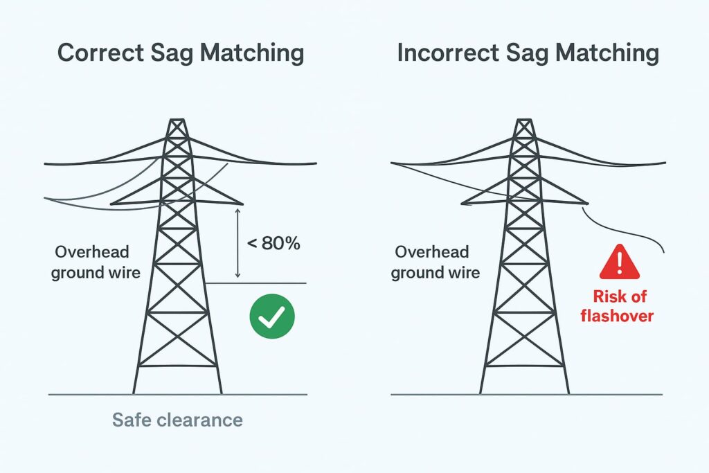
One of the most important design considerations is sag matching. Every suspended wire naturally sags between towers under its own weight. If the ground wire sags too much, it can come dangerously close to the conductors, increasing the chance of flashovers during storms.
For safety, engineers ensure that the ground wire sag is not more than 80% of the conductor sag at everyday operating conditions. This hidden design detail is vital for maintaining clearance and reliability.

Corrosion Resistance
Transmission lines traverse deserts, coastal belts, industrial areas, and forests—all of which pose unique corrosion challenges. Corrosion weakens wires over time, reducing their lifespan and reliability.
- Galvanized steel → Cost-effective, best for dry inland regions.
- Aluminum-clad steel (Alumoweld) → Excellent corrosion resistance, ideal for coastal and humid zones.
- ACSR/AW or AACSR/AW → Suited for industrial regions with chemical or acidic pollution.
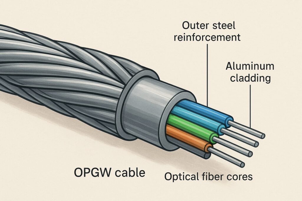
- OPGW (Optical Ground Wire) → Combines aluminum-clad steel with fiber optics, giving both strength and communication capability.
The choice of material is often a direct reflection of the environment the line passes through.
Current Carrying Capacity
During system faults, such as a short circuit, ground wires must carry large amounts of current safely. The wire must be sized not only for lightning interception but also for thermal performance under fault conditions.
- Galvanized steel and Alumoweld → Can withstand up to 400°C during faults.
- ACSR/AW and AACSR/AW → Typically limited to 200°C.
- OPGW → With aluminum-clad strands, can handle up to 300°C.
This ensures that even during extreme fault events, the ground wire does not weaken or fail.
Grounding and Location
Placement and grounding are just as important as material selection. The ground wire must always run above conductors to act as a shield. At each tower, proper grounding is essential.
In rocky or mountainous terrains, where soil resistivity is high, engineers install counterpoise wires or deep ground rods to improve earthing performance. A well-placed wire with poor grounding is ineffective—it must work as a complete system.
Fault Current and Distance Considerations
When a fault occurs, the distribution of current along the line is not uniform.
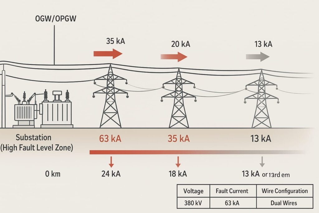
- Near the fault, the ground wire carries the maximum current.
- As the distance from the fault increases, more current escapes through towers and soil, reducing the burden on the wire.
This natural reduction allows engineers to optimize designs by using higher-rated ground wires near substations, where fault levels are greatest, and lighter wires in remote spans. This approach balances safety and cost efficiency.
Typical Ratings for Overhead Ground Wires
In practice, transmission engineers follow general guidelines for ground wire ratings based on voltage level and distance from substations. The closer the line is to a major substation, the higher the fault current rating required.
| Transmission Voltage Level | Typical Fault Current Range | Recommended Ground Wire Rating | Practical Application |
|---|---|---|---|
| 380 kV (Extra High Voltage) | Up to 63 kA | ~24 kA capacity within 10–12 km of substations; ~13 kA for remote spans | Dual wires often used (OGW + OPGW) for protection and communication |
| 230 kV (High Voltage) | Up to 63 kA | ~24 kA within 5–6 km of substations; ~13 kA farther along the line | Two shield wires are common, one often OPGW |
| 132–115 kV (Medium to High Voltage) | Up to 40 kA | Typically 24 kA near substations; 13 kA for remote spans | Usually one shield wire; sometimes OPGW added for communication |
| 69 kV (Sub-Transmission) | Up to 40 kA | Single wire rated for 13–24 kA, depending on local conditions | Used mainly for regional interconnections |

This tiered approach reflects a fundamental engineering principle: design heavier near fault sources, optimize farther away.
ALSO READ: Conductor Selection Considerations for Overhead Transmission Lines
The Rise of Optical Ground Wire (OPGW)
Traditional ground wires serve only as protective shields. However, with the growth of digital grids, the demand for communication within power networks has skyrocketed. This has led to the rise of Optical Ground Wire (OPGW).
OPGW combines the shielding ability of a ground wire with fiber optics inside its core. This makes it a dual-purpose solution:
- Lightning protection for the transmission system.
- Telecommunication backbone for SCADA, protection signaling, and monitoring.
Utilities now prefer OPGW in high-voltage and extra high-voltage systems because it enables real-time monitoring, fault detection, and communication—all without needing separate telecom cables.

Best Practices in Ground Wire Selection
From decades of field experience, some best practices have emerged that remain valid across regions:
- Always conduct fault current studies before deciding wire size.
- Match sag carefully—keep ground wire sag ≤80% of conductor sag.
- Select corrosion-resistant wires in coastal or polluted zones.
- Use dual ground wires (OGW + OPGW) in extra high-voltage lines.
- Balance fault current sharing by ensuring similar resistance when two wires are used.
- Think ahead—choose OPGW when future communication is needed.
Following these practices ensures not just immediate safety but also long-term reliability.
Real-World Example
Consider a 380 kV transmission line in a coastal region. Engineers here face:
- High salt spray corrosion from the sea.
- High fault currents near bulk substations.
The chosen solution might be:
- Alumoweld ground wire for corrosion resistance.
- OPGW for combined lightning protection and communication.
- 24 kA rated wires near substations, reducing to 13 kA wires for remote spans.
The result is a system that is resilient, economical, and ready for smart grid integration.
Future of Ground Wires
The overhead ground wire of tomorrow is not just a passive protector. Trends point towards smarter, more versatile designs:
- Hybrid OPGW with sensors for real-time fault, vibration, and temperature monitoring.
- Carbon composite cores to reduce sag while increasing tensile strength.
- High-temperature designs to survive extreme climates and higher fault currents.
- Renewable integration where OPGW doubles as the communication backbone for solar and wind projects.
The humble shield wire is steadily evolving into a multifunctional smart component of the transmission grid.
Frequently Asked Questions (FAQs)
Q1: What is the main function of an overhead ground wire?
Its primary role is to intercept lightning strikes and safely conduct them into the ground, protecting phase conductors.
Q2: What is the difference between OGW and OPGW?
OGW provides only lightning protection, while OPGW offers both protection and fiber optic communication.
Q3: Why does sag matching matter?
Improper sag matching can cause ground wires to approach conductors, increasing the risk of flashovers during storms.
Q4: Which ground wire material is best in coastal regions?
Aluminum-clad steel (Alumoweld) or OPGW, because they offer excellent resistance to salt corrosion.
Q5: Do utilities use different wire sizes on the same line?
Yes. Larger wires are often installed near substations, while smaller wires are used in remote spans to optimize cost.
Q6: Why are two ground wires sometimes used?
Dual ground wires improve lightning shielding and provide redundancy. One may also be OPGW to carry communication.
Conclusion
The Overhead Ground Wire (OGW) may seem like a small addition to massive transmission towers, but it is one of the most important components of the grid. From shielding lines against lightning to carrying fault currents and even enabling communication through OPGW, it ensures that electricity flows safely and reliably across regions.
Selecting the right ground wire is a combination of engineering science and practical judgment. By considering sag, corrosion resistance, fault currents, grounding quality, and future communication needs, utilities can build systems that are not only reliable today but also resilient for decades to come.
The next time you glance at a transmission tower, remember: that small wire at the very top may not deliver electricity to your home, but without it, your lights might not stay on.


Interesting and educational.
Thank you very much Walter.
Pingback: Sag and Tension Calculation in Overhead Transmission Lines – Complete Guide with Shielding Angle Concept - ohtldesign.com Sag and Tension Calculation – Transmission Lines | OHTL Design