Overhead transmission lines are the backbone of modern power systems, carrying bulk electricity across long distances. Before any conductor or OPGW (Optical Ground Wire) is strung between two towers, engineers must carefully calculate sag and tension.
Sag and tension calculation is not just about stretching a wire between towers—it is about ensuring mechanical safety, electrical reliability, and lightning protection. Without proper calculations, the line may face clearance violations, snapping, tower stress, or lightning-induced outages.
In this guide, we will cover:
- What sag and tension mean in transmission lines.
- Why sag–tension calculations are mandatory.
- Environmental and thermal effects on conductors.
- The importance of sag–tension in OPGW (Optical Ground Wire).
- The Shielding Angle concept with reference to standards.
- Consequences of ignoring sag–tension design.
- Step-by-step PLS-CADD tutorial for sag–tension calculation.
- Practical design recommendations for reliability.
🔹 What is Sag in Transmission Lines?
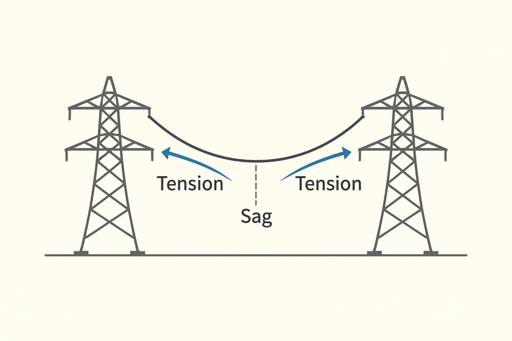
When a conductor or OPGW is suspended between two towers, it naturally bends downward under its own weight. The vertical distance between the point of suspension (tower cross-arm) and the lowest point of the conductor curve is called sag.
- Excessive sag → conductor comes closer to the ground → clearance violation.
- Too little sag → conductor is overstressed → may snap during temperature or wind variations.
Thus, sag must be optimized—not too high, not too low.
🔹 What is Tension in Transmission Lines?
Tension is the pulling force exerted on a conductor or OPGW when stretched between towers.
- High tension: Conductor is tight → higher stress on towers, insulators, and conductor material.
- Low tension: Conductor hangs loose → sag increases, leading to clearance problems.
👉 Relationship: Sag and tension are inversely related.
- Higher tension → lower sag.
- Lower tension → higher sag.
This balance is at the heart of every sag–tension calculation.

🔹 Why Are Sag and Tension Calculations Important?
1. Maintaining Electrical Clearance
Conductor clearance must always meet safety standards:
- Minimum clearance above ground, rivers, or roads.
- Clearance from buildings, trees, or other structures.
Improper sag could lead to flashovers, accidents, or outages.
2. Mechanical Safety of Line Components
Towers and insulators are designed to handle certain loads. Excessive tension can overstress hardware, leading to mechanical failures.
3. Temperature Effects
Conductor length changes with temperature:
- High temperature → expansion → sag increases.
- Low temperature → contraction → tension increases.
Design must account for both summer max and winter min conditions.
4. Wind and Ice Loading
Wind applies horizontal pressure, while ice accumulation increases conductor weight. Both factors alter sag and tension.
5. OPGW (Optical Ground Wire) Requirements
OPGW performs dual roles:
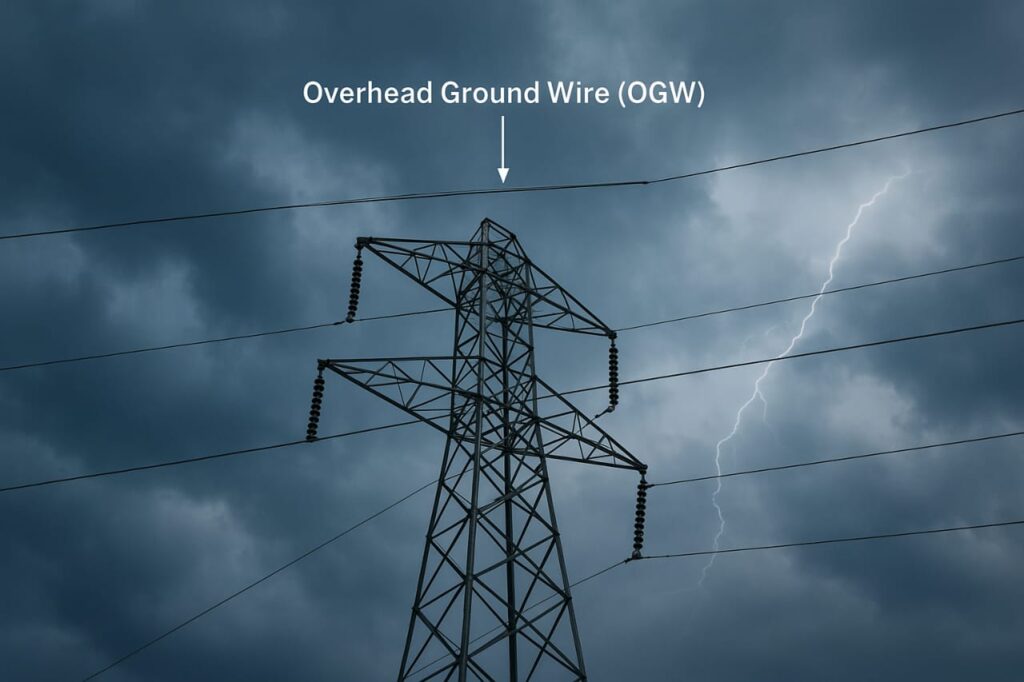
- Lightning protection (like earth wire).
- Fiber optic communication (housing delicate optical fibers).
If sag and tension are not correct:
- Excessive stress may break fibers inside OPGW.
- Wrong sag can disturb the shielding angle, reducing lightning protection.

🔹 The Shielding Angle Concept
One of the most important aspects of OPGW design is the shielding angle.
What is Shielding Angle?
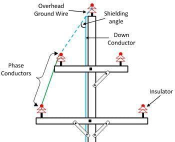
The shielding angle is the angle between:
- A vertical line passing through the tower top, and
- A line drawn from the OPGW to the outermost phase conductor.
- Smaller shielding angle → better protection.
- Larger shielding angle → weaker protection.
ALSO READ: Overhead Ground Wire Selection in Transmission Lines: A Complete Guide
SEC Standard: 20° Shielding Angle
According to the SEC standard, the shielding angle should not exceed 20° for a 380kV transmission line(whereas for all other transmission lines 69kV to 230kV, the shielding angle shall be 30 degrees or less, provided that the outage rate due to lightning shall not exceed the maximum limit defined).
This ensures all phase conductors fall within the protective zone of OPGW.
👉 If sag is incorrectly calculated, the OPGW may hang lower, increasing the shielding angle above 20°, exposing phase conductors to lightning.
Why the 20° Shielding Angle is Critical
- Improved Lightning Protection – Reliable path for lightning discharges, minimizing flashovers.
- Reduced Outage Probability – Poor shielding leads to frequent lightning faults.
- System Reliability – Correct sag–tension ensures maximum uptime.

🔹 Consequences of Ignoring Sag–Tension and Shielding Angle
- Ground clearance violations → safety hazards.
- Mechanical stress failures → conductor snapping, tower or insulator damage.
- Fiber breakage in OPGW → loss of communication and SCADA systems.
- Excessive shielding angle (>20°) → lightning directly striking conductors.
🔹 Practical Design Recommendations
- Always perform sag–tension calculations at:
- Maximum operating temperature.
- Minimum operating temperature.
- Wind and ice load conditions.
- Verify OPGW sag carefully to keep shielding angle ≤ 20° (SEC standard).
- Use stringing charts and correction tables during erection.
- Maintain a balance: safe clearance + safe tension = long-term reliability.
🛠️ Step-by-Step Tutorial: Sag & Tension Calculation in PLS-CADD
Now that we understand the theory, let’s move to practical calculation in PLS-CADD.
1️⃣ Open Your Project
- Launch PLS-CADD.
- Open Demo Line Example (File → Open → Demo Line).
- This gives you a model with terrain, structures, and conductors.
2️⃣ Define Conductor Properties
- Go to Criteria → Cables.
- Choose a standard conductor (e.g., ACSR Drake).
- Ensure diameter, RTS, creep data, and thermal expansion are correct.
👉 Without conductor data, sag–tension cannot be computed.
3️⃣ Define Weather Cases
- Go to Criteria → Weather Cases.
- Add conditions like:
- 25°C, no wind, no ice (installation).
- -5°C, wind + ice (final).
- 75°C, no wind (hot).
- Save as Project.wca.
4️⃣ Define Tension Sections
- Go to Sections → Tension Sections.
- Select start and end structures (usually dead-end towers).
- PLS-CADD groups spans into sections automatically.
5️⃣ Perform Sag–Tension Calculations
- Go to Sections → Sag/Tension.
- Select method:
- Ruling Span Method (Level 1) – good for beginners.
- Finite Element Method (Level 2–4) – advanced.
- Enter stringing tension (e.g., 20% RTS).
- Click Calculate.
👉 You’ll get sag (m), horizontal tension (kN), vertical load, etc.
6️⃣ Visualize Sag
- Go to Graphics → Profile View.
- Toggle between weather cases (hot, cold, windy).
- Notice sag increases in hot weather and tension increases in cold/wind.
7️⃣ Generate Stringing Charts
- Go to Reports → Stringing Charts.
- Choose conductor + tension section.
- Export to PDF/Excel → these charts guide field crews.
8️⃣ Check Clearances
- Go to Sections → Clearances.
- Ensure sag values respect:
- Ground clearance.
- Road/river crossings.
- Vegetation or obstacles.
✅ Example Practice
- Open Demo Line.
- Assign ACSR Drake.
- Define 3 weather cases.
- Create 1 tension section.
- Run sag–tension at 20% RTS.
- Compare sag at mid-span under hot vs cold conditions.
🔎 Conclusion
Sag and tension calculation is the foundation of transmission line safety. For both conductors and OPGW, engineers must ensure:
- Sag is within limits.
- Tension does not overstress hardware.
- OPGW shielding angle ≤ 20° (SEC standard) for lightning protection.
With tools like PLS-CADD, engineers can perform accurate sag–tension calculations, verify clearances, and generate stringing charts for construction.
✅ Too much sag = clearance issues.
✅ Too much tension = snapping risk.
✅ Wrong shielding angle = lightning problems.
A well-designed sag–tension profile ensures overhead transmission lines operate safely, efficiently, and reliably for decades.


Thank you for all the information that we benefit from in our professional life 🙏
You are welcome Sir.
Thank you for your kind words.
Dear Sir Transmission line senior Supervisor Erection and stringing incharge
66/132/220/400/765/ KV / HVDC
Thank you
Hi,
The key point in line design is to estimate the sag after creep.
Exactly. Estimating sag after creep is a key design step, since conductors gradually elongate under sustained tension. That’s why line design considers initial sag, final sag (with creep), and everyday operating conditions. Ignoring creep can lead to unexpected clearance issues and reliability risks in the long run.
Great initiative & willing to learn more on such topics💐
THANK YOU VERY MUCH
I need the formula of Sag and Tension in transmission line and the maximum and minimum value for both ? thanks