

OHTL Construction · Engineering Case Study · 6 November 2026
Building a new 380 kV overhead transmission line (OHTL) across existing 132 kV circuits is one of the hardest jobs in line construction. It gets harder when one of those circuits stays energized and a major road runs through the same crossing.
This field case study shows how that crossing was engineered and built: eleven mobile cranes, more than two months of earthworks for crane platforms at two different elevations, tower erection beside live infrastructure, and a multi-crane pilot rope transfer using man baskets before conductor stringing.
If you design, plan or supervise OHTL construction, the main lesson is simple. The temporary construction stages, not only the final line, decide whether a crossing is safe and buildable.
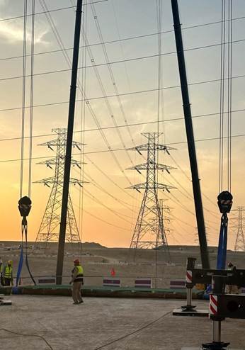
Crane hooks rigged on a prepared working platform, with the existing 132 kV towers in the background.
Project at a Glance
The crossing combined three interfaces in one corridor: a live circuit, an isolated circuit and a major road.
| Item | Detail |
| New line | 380 kV overhead transmission line |
| Crossed infrastructure | Two parallel 132 kV circuits and a major road |
| Circuit status | One 132 kV circuit energized throughout; one de-energized under approved isolation |
| Cranes for line crossing | 7 mobile cranes, 160 t nominal each |
| Cranes for road crossing | 4 mobile cranes, 50 t nominal each |
| Total cranes | 11 |
| Ground preparation | More than 2 months of cutting, filling, leveling and compaction |
| Working elevations | A valley and an elevated plateau |
| Stringing equipment | Pulling and tensioning machines rated 90 to 160 kN |
| Key method | Multi-crane protective arrangement and man-basket pilot rope transfer |
Why Crossing Live Transmission Lines Is So Demanding
A conventional tower erection job has open ground, free crane movement and no electrical neighbors. A crossing over energized lines removes all three. The crew faces:
- Limited space for crane positioning and movement
- Different ground elevations and restricted access
- Electrical approach limits around energized conductors
- Temporary lifting configurations during tower erection
- Controlled transfer of the pilot rope, followed by conductor stringing
- Coordination with existing road and transmission infrastructure
The most important point is easy to miss. The final line configuration is not always the most demanding condition. Tower erection, lifting, pilot rope transfer and conductor pulling each create temporary positions, loads and clearances that need their own assessment.
Site Constraints and Crane Platform Preparation
A restricted site at two elevations
The natural ground could not provide the level working areas the cranes needed. The available space was split between a valley and an elevated plateau, so the team could not simply drive in and set up.
Instead, the project built its own crane positions. Earthworks ran for more than two months and included:
- Cutting and excavation to reach the required ground levels
- Filling to extend the working areas
- Leveling and shaping each crane location
- Compaction of the prepared areas
- Field compaction tests at the designated crane locations
The crossing drawings show how large the level difference was. In the left-side circuit section, one crane platform is marked at about 818.3 m ground elevation and another at about 801.8 m, a gap of roughly 16 m between crane positions across the same crossing.
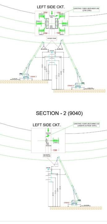
Crossing section showing crane platforms at different elevations and the live and outage 132 kV circuits.
Compaction is not the same as bearing capacity
A crane platform is more than a graded patch of ground. Through its outriggers, a crane passes large and changing loads into the soil. Those reactions depend on boom length, working radius, lifted load, counterweight and lifting direction.
A sound platform assessment covers six checks:
- Platform geometry and working level
- Soil type and bearing capacity
- Expected outrigger reactions against allowable ground pressure
- Differential settlement and platform deformation
- Slope stability and edge distance
- Drainage, erosion and changes in ground conditions
A passed field density test shows that the compaction criteria were met at the tested spot. It does not prove the ground can carry every crane reaction in the worst operating configuration. Compaction results should always be read together with geotechnical data, crane load data, the platform design and the approved lifting plan.
The lesson: temporary working platforms are part of the lifting engineering, not a civil afterthought.
Crane Deployment Strategy for the Crossing
Eleven mobile cranes were deployed, split by the job each crossing demanded.
| Application | Cranes | Nominal capacity |
| 380 kV line crossing activities | 7 | 160 t each |
| Major road crossing | 4 | 50 t each |
| Total | 11 |
For the 160 t fleet, the reported working configurations were:
| Arrangement | Cranes | Working radius | Working height |
| Configuration A | 4 | 12 m | 62 m |
| Configuration B | 2 | 26 m | 74 m |
| Additional crane | 1 | Per approved lifting plan | Assigned to the de-energized circuit crossing |
The plan view in the drawing set shows the cranes arranged around the new line crossing, with offsets of 20 m and 15 m marked on each side of the existing line.
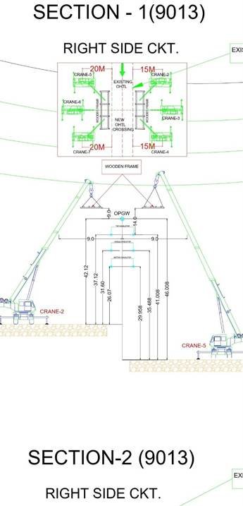
Plan and section of the multi-crane arrangement at the crossing.
Capacity at radius, not nameplate capacity
A 160 t crane is not a 160 t crane at every radius. The same machine at a 12 m radius and at a 26 m radius has very different permitted loads. The real limit comes from the manufacturer’s load chart, for the exact boom length, counterweight, outrigger setup and operating conditions.
With several cranes working in a tight corridor, planners must also control:
- Boom-to-boom interference
- Tail-swing clearance
- Suspended load travel paths
- Simultaneous lifting coordination
- Radio communication between operators and lifting supervisors
- Exclusion zones and emergency stop arrangements
Crane selection and positioning are one engineering exercise. Choosing by nominal capacity alone, without ground and geometry checks, can produce an arrangement that does not work.
Tower Erection Beside Existing 132 kV Circuits
Tower erection came first in the crossing sequence, before any conductor stringing. The lifting plan had to be built around the status of each existing circuit:
- The energized circuit was a continuous electrical constraint. Crane booms, lifting accessories, tower components and suspended loads all had to stay inside the authorized working limits.
- The de-energized circuit required the approved isolation, grounding and permit-to-work arrangements. Its status had to be formally verified and maintained under the operating authority’s procedures.
The lifting envelope also changes during the lift. Boom, hook and load move through many positions between pick-up and final placement. A sound lifting study therefore checks the complete load path, not only the final position. The same applies to crane repositioning and boom changes: every configuration must be covered by the approved lifting documentation.
Multiple mobile cranes working together in a restricted corridor under approved lifting plans.
Pilot Rope Transfer With Cranes, Wooden Frames and Man Baskets
The most distinctive part of this job was how the pilot rope was taken across the crossing. It was a coordinated multi-crane operation:
- Four cranes were positioned to provide the protective and supporting arrangement before and after the crossing.
- Two cranes carried personnel baskets as part of the transfer.
- The two elevated baskets were brought to the planned transfer position so the pilot rope could pass across the crossing.
- The pilot rope then became the first element of the stringing sequence, ahead of the conductor pulling.
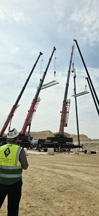
The drawings show wooden frames slung from the crane booms near the crossing, and a man basket with a roller on the crane serving the de-energized circuit. The photo below shows the same arrangement on site.
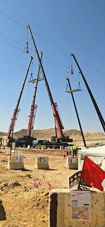
Man baskets and wooden frames raised by mobile cranes for the pilot rope transfer at the crossing.
What this operation demands
Working with personnel baskets near overhead electrical infrastructure needs a dedicated engineering assessment and specific authorization. It should cover:
- The basket system and lifting configuration
- Personnel protection
- Electrical approach limits
- Communication arrangements
- Rescue provisions
- Emergency response
The rope path also needs control. The pilot rope moves during the transfer and the later pulling stages, so its route must be managed to prevent contact with existing infrastructure or entry into restricted electrical approach zones. Close coordination between crane operators, lifting supervisors, the stringing team and safety personnel is essential.
Conductor Stringing and Tension Control
After tower erection, conductors were installed with pulling and tensioning equipment rated from 90 to 160 kN. The sequence started with the pilot rope, then moved to the pulling operations that bring the conductors into place.
Machine rating is only one limit. The suitability of the stringing arrangement depends on the whole system: rope, conductor, running blocks, connectors, anchorages and associated equipment. Equipment capacity alone does not prove the arrangement is suitable.
The engineering review should cover:
- Maximum expected pulling tension
- Equipment and rope working-load limits
- Conductor mechanical limits
- Running-block and sheave suitability
- Temporary sag and conductor movement
- Crossing-span geometry
- Communication between pulling and tensioning stations
- Emergency stopping and controlled release procedures
Clearance checks must also cover the temporary stages. During stringing, conductors sit at different heights and tensions than in the final sag condition. This matters most where an existing circuit stays energized for the whole operation.
Crossing a Major Road During Construction
The crossing also passed over a major, operationally important road. Four 50 t mobile cranes were allocated to this part of the work.
Road crossings bring a different set of constraints from line crossings. Besides lifting safety, the team must handle:
- Traffic management plans
- Road authority approvals
- Vehicle movement restrictions
- Exclusion zones
- Protection of road users
The lifting sequence has to match the approved traffic management arrangement, so that no vehicle can enter the area under a suspended load or inside a restricted lifting zone. For that reason the road crossing used its own construction and lifting arrangement, not a copy of the line crossing method.
Electrical Safety and Construction Risk Management
Risk near an energized circuit is not limited to touching a conductor. Booms, suspended loads, lifting accessories, ropes, pilot lines and newly installed conductors can all approach live equipment unintentionally. The risk assessment should address six areas.
| Risk area | What to control |
| Electrical approach limits | Minimum approach distances and working boundaries set by the applicable Saudi Electricity Company requirements and the operating authority |
| Crane and load movement | Full movement envelope, boom deflection, load swing, uncontrolled movement and simultaneous crane operations |
| Circuit isolation | Approved isolation, grounding and permit-to-work, with status confirmed by authorized personnel before work starts |
| Temporary stringing arrangements | Pilot rope, pulling rope and conductor paths, temporary sag and deviation from the planned route |
| Weather and environment | Wind speed, visibility and ground conditions, with work limits from approved procedures and manufacturer requirements |
| Emergency response and stop-work authority | Clear communication, emergency procedures, and reassessment whenever the approved plan is departed from |
The central lesson: the energized status of the existing circuit is a continuous engineering constraint, not just a permit condition.
Engineering Lessons Learned
- Temporary works can control the schedule. The two months spent on crane platforms were a major activity in the programme. Start crane position planning early, not when the cranes arrive.
- Ground preparation and crane selection depend on each other. A crane with enough lifting capacity can still be wrong for a location if the platform cannot carry its outrigger reactions or the geometry blocks the needed configuration.
- Every construction stage needs its own clearance check. The final conductor arrangement does not represent the temporary conditions during erection and stringing, especially next to a live circuit.
- Multi-crane operations need detailed coordination. Crane positions, boom envelopes, suspended loads and personnel access must be reviewed together before execution.
- Civil, lifting, stringing and electrical teams work as one system. Civil teams build the platforms, lifting engineers set crane configurations and load paths, stringing engineers control pulling and tensioning, and electrical operations set the authorized boundaries. None of these can be planned in isolation.
Standards and Engineering References
Work like this must follow the applicable Saudi Electricity Company specifications, project technical requirements, approved method statements, risk assessments and operating authority instructions. The following international publications give supporting guidance:
| Standard | Relevance |
| IEC 60826 | Design criteria of overhead transmission lines |
| EN 50341-1 | General requirements for overhead electrical lines exceeding AC 1 kV |
| IEEE Std 524 | Guide to the installation of overhead transmission line conductors |
| IEC 61936-1 | Power installations exceeding 1 kV AC and 1.5 kV DC |
For lifting, also follow the crane manufacturer’s instructions, approved load charts, project lifting procedures and relevant crane safety standards. These references do not replace SEC requirements or approved project documents. Check the edition, clauses and applicability before using any of them as a compliance basis.
Frequently Asked Questions
Can a new transmission line cross an energized 132 kV line?
Yes, with a controlled method. The crossing needs approved electrical approach limits, a lifting plan covering every crane position and load path, and continuous coordination with the operating authority. In this case one 132 kV circuit stayed energized while the other was isolated.
Why use so many cranes for one OHTL crossing?
The site had limited space, two ground elevations and several simultaneous tasks. Seven 160 t cranes handled the line crossing, including the protective arrangement and man baskets, and four 50 t cranes handled the road crossing.
Is a compaction test enough to approve a crane platform?
No. A compaction test shows the ground met the density criteria at the tested location. Bearing capacity, outrigger reactions, settlement and slope stability must be checked separately against the crane load data and the lifting plan.
Why are temporary stringing conditions important?
During pilot rope transfer and conductor pulling, ropes and conductors sit at different heights and tensions than in the final line. Clearances to an energized circuit must be checked at every stage, not only in the final sag condition.
What equipment strings conductors across a crossing?
Here, pulling and tensioning machines rated 90 to 160 kN were used. The suitability of the whole system, including rope, blocks, connectors and anchorages, matters more than the machine rating alone.
Conclusion
Crossing two 132 kV circuits and a major road with a new 380 kV line took eleven cranes, platforms built at two elevations over two months, tower erection beside live infrastructure, and a carefully controlled pilot rope and stringing sequence.
The key takeaway: a successful OHTL crossing is not won by choosing the biggest cranes or by relying on final line clearances. It is won by engineering control of every temporary stage, from ground preparation to the last conductor.
Have you faced a similar live-line crossing? Explore more transmission line design and construction articles on OHTL Design, or contact us to discuss your project.

Eng. Mohamed Essam
Senior Civil Construction Engineer | Infrastructure & OHTL SpecialistNationality: Egyptian
LinkedIn Profile
Eng. Mohamed Essam is a Civil Engineer with over 10 years of experience in the execution and management of infrastructure projects, including substation works and high-voltage transmission lines (OHTL). He is currently leading the execution of a 380 kV Transmission Tower project within the Qiddiya Project in Riyadh, one of the Kingdom’s most prominent national initiatives.
Known for precision in field execution, strong coordination with technical teams, and a solid commitment to the highest standards of quality and safety.