A practical, field-tested guide to how tower type, body extension, leg extension, and stub setting are really decided on 380kV overhead transmission line projects — aligned with Saudi Electricity Company (SEC) Standards and Project Technical Specifications (PTS).
Why 380kV OHTL Tower Selection and Stub Setting Matter
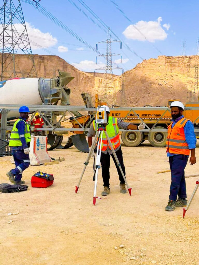
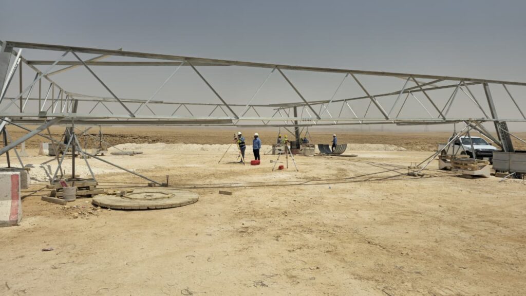
On any 380kV Extra High Voltage (EHV) overhead transmission line, the tower foundation is where structural engineering meets the reality of the construction site. Get the stub position, inclination, or spacing even slightly wrong, and the consequences ripple outward — erection delays, rework, and in the worst cases, compromised structural performance.
A persistent misconception on many project sites is that the Stub Setting Template Drawing determines tower type, body extension, and leg extension. It doesn’t. Those decisions are locked in much earlier, during mechanical design and tower spotting, then carried forward through a defined chain of engineering documents until they finally reach the construction crew.
This guide walks through that full workflow — from route selection to tower erection — using a real 380kV double-circuit project in Saudi Arabia as a working example.
The 380kV OHTL Engineering Document Hierarchy
Every stage of an OHTL project produces a document that feeds directly into the next. Skip a step, or read one out of order, and misinterpretation follows.
| Stage | Engineering Document | What It Actually Controls |
| 1 | Route Selection Study | Corridor optimization |
| 2 | Plan and Profile Drawing | Tower positioning |
| 3 | Structure Data List (SDL) | Structural configuration |
| 4 | Tower Loading Schedule | Foundation design inputs |
| 5 | Tower Outline Drawing | Tower geometry |
| 6 | Foundation Design & Drawing | Civil foundation design |
| 7 | Stub Setting Template Drawing | Construction control |
| 8 | Tower Erection Drawing | Steel assembly |
None of these documents stands alone. Each exists because the stage before it produced the information it needs.
Step 1: Route Selection for 380kV Transmission Lines
Before any tower geometry is considered, the corridor itself has to be optimized against environmental limits, existing infrastructure, terrain, and room for future expansion — all while staying buildable and accessible for construction crews.
Step 2: Tower Spotting — Where Structural Configuration Is Actually Decided
Once the corridor is fixed, tower spotting begins, typically using PLS-CADD, PLS-TOWER, or PLS-POLE. This is where the real structural configuration for each tower location is determined, balancing mechanical, electrical, and economic constraints together.
The spotting process weighs several factors simultaneously:
- Line deviation angle — the transverse load the structure must resist
- Ground profile — elevation changes along the route
- Electrical clearances — the safety margins that must be maintained
- Weight span and wind span — vertical and transverse loading drivers
- Ruling span and foundation optimization — economic and structural efficiency
How Deviation Angle Sets the Tower Family
| Tower Family | Typical Deviation Range |
| Suspension Towers | 0°–2° |
| Small Angle Towers | 2°–10° |
| Medium Angle Towers | 10°–35° |
| Large Angle Towers | 35°–60° |
| Heavy Angle Towers | 60°–90° |
Weight span drives compression reactions and bearing pressures at the foundation. Wind span drives uplift and overturning moments. Clearance requirements — over highways, existing lines, pipelines, wadis, or industrial facilities — often push the design toward body extensions.
Body Extension vs. Leg Extension: The Distinction That Gets Confused Most
This is one of the most common sources of confusion on site, so it’s worth separating clearly.
Body extension is a uniform increase to the tower body, applied during tower spotting to improve electrical clearance. Because it changes overall tower height, it also affects structural loading and tower weight — it’s genuinely part of the mechanical design, not a construction-stage adjustment.
Leg extension, by contrast, is applied individually to each leg to handle variations in ground elevation on sloping terrain. It does not change overall tower height and does not improve clearance. Its only job is to keep tower geometry correct and ensure loads transfer properly into the foundation despite uneven ground.
Same word family, completely different purpose. Confusing the two is where a lot of field errors start.
Stub Setting Philosophy: Why Stubs Are Installed at an Incline
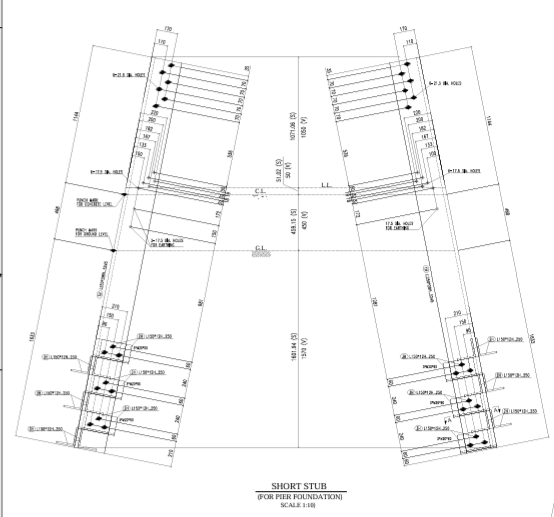
Tower stubs are deliberately installed with an inward inclination that mirrors the inclination of the tower legs. This isn’t arbitrary — it keeps structural loads predominantly axial, which minimizes bending moments and reduces eccentricity at the connection.
The Stub Setting Template exists to hold that geometry in place during construction. It’s a temporary precision jig that preserves:
- Leg spacing
- Diagonal geometry
- Inclination angles
- Tower orientation during concrete placement
It’s worth repeating the core point here: the template is a construction control tool, derived from already-approved structural and foundation design. It doesn’t define anything — it enforces what’s already been decided upstream.
Case Study: New Qiddiyah to Al Jillah 380kV Double-Circuit OHTL
This workflow played out on a real project — construction of a 380kV double-circuit OHTL from New Qiddiyah BSP #9078 to Al Jillah BSP #9063 in Saudi Arabia, executed under SEC standards and Project Technical Specification PTS-19CO326.
What the Structure Data List Provided
Within the Plan and Profile package, the SDL laid out, for every tower:
- Tower number and type
- Coordinates and ground elevation
- Body extension
- Leg extension
- Wind span and weight span
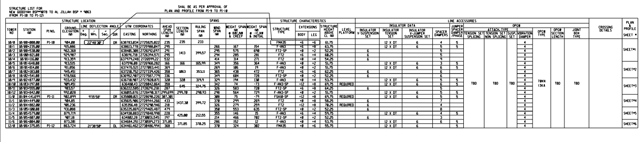
Structures in the PI10–PI12 section, for example, used combinations of FT2, F-AN3-SP, and FSA10 tower families, selected according to route geometry, mechanical loading, and clearance needs.
The Engineering Decision Sequence on Site
- Review the Structure Data List
- Verify tower type
- Verify body extension
- Verify leg extension
- Pull the corresponding Tower Outline Drawing
- Review the Foundation Drawing
- Select the correct Stub Setting Template
- Perform survey layout and orientation
- Install and verify the stubs
- Complete inspection before concrete placement
- Proceed with tower erection after foundation acceptance
Follow this order, and the paperwork does what it’s supposed to do — prevent errors rather than cause them.
Common Mistakes in 380kV OHTL Tower and Stub Documentation
Most construction mistakes on these projects don’t come from bad engineering — they come from engineers looking in the wrong document for the wrong answer.
| The Mistaken Belief | Where the Answer Actually Lives |
| “The template determines tower type” | Structure Data List |
| “The foundation drawing determines body extension” | Structure Data List |
| “The tower outline determines tower location” | Plan and Profile Drawing |
| “The stub template determines leg extension” | Structure Data List |
Notice the pattern: the Structure Data List is the real source of truth for almost all of these. Everything downstream of it is execution, not decision-making.
Frequently Asked Questions
Does the Stub Setting Template determine the tower type?
No. Tower type is determined during tower spotting and recorded in the Structure Data List. The Stub Setting Template is a construction control drawing derived from already-approved design, not a design document itself.
What is the difference between body extension and leg extension on a transmission tower?
Body extension is a uniform increase to the tower body applied to improve electrical clearance, and it changes overall tower height. Leg extension is applied individually per leg to compensate for uneven ground and does not change tower height or clearance.
What software is used for tower spotting on 380kV OHTL projects?
Tower spotting is typically performed using PLS-CADD, PLS-TOWER, and PLS-POLE, balancing deviation angle, ground profile, electrical clearance, weight span, and wind span.
Why are tower stubs installed at an incline?
Stubs are installed with an inward inclination that matches the tower leg inclination so that structural loads remain predominantly axial, minimizing bending moments and connection eccentricity.
What document is the real source of truth for tower type, body extension, and leg extension?
The Structure Data List (SDL), which is generated from the tower spotting and mechanical design process and communicated through the Plan and Profile package.
Key Takeaway
Tower type, body extension, and leg extension are all locked in during tower spotting and mechanical design — and the Structure Data List is what carries those decisions forward. The Stub Setting Template is not a design document. It’s a precision construction aid that translates already-approved engineering decisions into an accurate physical result on site.
The full 380kV OHTL workflow, start to finish:
Route Selection → Tower Spotting → Structure Data List → Tower Loading Schedule → Tower Outline Drawing → Foundation Design → Stub Setting Template → Foundation Construction → Tower Erection
Understanding where each document sits in that chain — and just as importantly, what it doesn’t control — is one of the simplest ways to cut down on rework and keep a 380kV OHTL project on schedule.
References
- IEC 60826 — Design Criteria of Overhead Transmission Lines
- ASCE Manual 74 — Guidelines for Electrical Transmission Line Structural Loading
- IEEE Guide for Transmission Structure Design
- Saudi Electricity Company Transmission Engineering Standards (TES)
- Saudi Electricity Company Transmission Material Standard Specifications (TMSS)
- Project Technical Specification PTS-19CO326 for 380kV OHTL Projects
- PLS-CADD User Manual
- PLS-TOWER User Manual
CIGRE Technical Brochures on Overhead Transmission Line Design

Eng. Mohamed Essam
Senior Civil Construction Engineer | Infrastructure & OHTL SpecialistNationality: Egyptian
LinkedIn Profile
Eng. Mohamed Essam is a Civil Engineer with over 10 years of experience in the execution and management of infrastructure projects, including substation works and high-voltage transmission lines (OHTL). He is currently leading the execution of a 380 kV Transmission Tower project within the Qiddiya Project in Riyadh, one of the Kingdom’s most prominent national initiatives.
Known for precision in field execution, strong coordination with technical teams, and a solid commitment to the highest standards of quality and safety.