Introduction to Transmission Tower Foundation Design
Transmission line tower foundations are among the most critical elements in overhead transmission line engineering. Unlike conventional building foundations, transmission tower foundations are subjected to highly variable and extreme loading conditions including compression, uplift, lateral loads, wind forces, and overturning moments.
For high-voltage transmission systems such as 380kV lattice steel towers, foundation stability is essential to ensure long-term structural reliability and operational safety.
This article presents a scientific and detailed explanation of the pier foundation design calculation for a 380kV lattice steel tower Type F-SA10/SP. The design methodology follows internationally recognized engineering standards including:
- ACI 318
- IEEE 691
- Bowles Foundation Design
- Tomlinson Foundation Engineering
- Poulos & Davis
- Terzaghi & Peck
These standards represent advanced geotechnical and structural engineering principles used worldwide in transmission line foundation design.
Why Pier Foundations Are Used for 380kV Transmission Towers
Difference Between Pad Foundations and Pier Foundations
Pad Foundations
Pad foundations primarily rely on:
- Self-weight
- Surface bearing capacity
They are suitable for:
- Moderate tower loads
- Good bearing soils
- Low uplift conditions
However, for heavy transmission towers subjected to severe uplift and overturning forces, shallow foundations may become uneconomical or unsafe.
Pier Foundations
Pier foundations are deep foundations that resist loads through:
- Shaft skin friction
- Rock socket bonding
- Deep embedment resistance
- End bearing capacity
Pier foundations are preferred when:
- Tower loads are extremely high
- Significant uplift forces exist
- Rock strata are available
- Heavy angle or tension towers are used
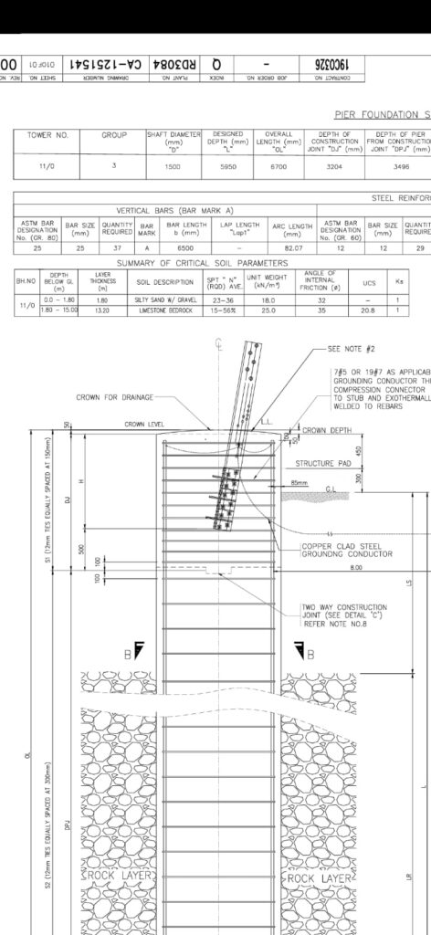
For the 380kV tower Type F-SA10/SP, the applied loading conditions were:
- Compression Load: 2336.88 kN
- Uplift Load: 1903.78 kN
Due to these severe loading conditions, a rock-socketed pier foundation was selected as the safest and most economical solution.
Structural Behavior of the Pier Foundation
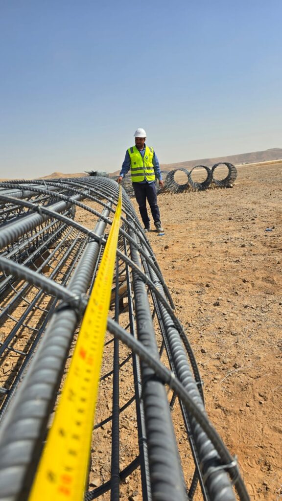
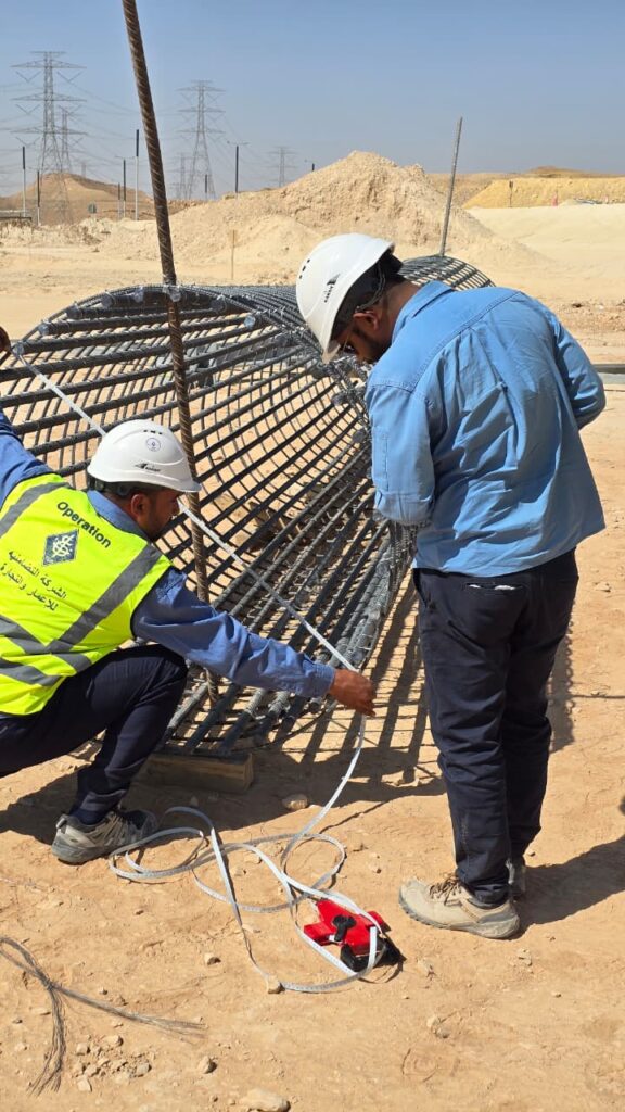
The pier foundation behaves as a reinforced concrete shaft deeply embedded into soil and rock.
The shaft resists structural loads through multiple mechanisms.
1. Skin Friction Resistance
Skin friction develops along the shaft surface due to:
- Soil-concrete interaction
- Rock-concrete adhesion
Skin friction increases with:
- Greater embedment depth
- Larger shaft diameter
- Improved rock roughness
This mechanism is particularly important for resisting uplift forces.
2. End Bearing Resistance
End bearing resistance develops at the base of the shaft where compressive loads are transferred directly to the rock layer.
Strong rock formations provide exceptionally high compressive resistance and minimize settlement.
3. Passive Lateral Resistance
The surrounding soil and rock provide passive resistance against lateral shaft movement caused by:
- Wind loading
- Conductor tension
- Broken wire conditions
This improves the lateral stability of the transmission tower foundation.
Design Loads Considered in the Foundation Analysis
The foundation design begins with the ultimate support reactions obtained from structural analysis.
| Load Type | Value |
|---|---|
| Compression Load | 2336.88 kN |
| Uplift Load | 1903.78 kN |
| Resultant Shear Load | 667.518 kN |
Compression Loads
Compression loads originate from:
- Tower self-weight
- Conductors
- Insulators
- Vertical loading effects
These loads are transferred safely into the rock strata through the pier shaft.
Uplift Loads
Uplift loading is one of the most critical design conditions for transmission towers.
These forces are generated by:
- Conductor tension
- Wind loading
- Line deviation angles
- Broken wire conditions
If not properly designed, uplift forces may cause pull-out failure of the entire foundation system.
Lateral Loads
Lateral forces are generated due to:
- Wind action
- Transverse conductor loads
- Unbalanced line conditions
These loads create:
- Shaft bending
- Lateral displacement
- Overturning moments
Therefore, lateral resistance analysis is a major component of transmission tower foundation engineering.
Soil and Rock Investigation
A proper geotechnical investigation is essential for safe foundation design.
The subsurface profile consisted of two primary layers.
Layer 1 – Frictional Soil
Thickness: 1.8 m
Properties:
| Property | Value |
|---|---|
| Friction Angle | 32° |
| Unit Weight | 18 kN/m³ |
Importance of Soil Friction Angle
The internal friction angle represents the shear resistance capacity of the soil.
Higher friction angles indicate:
- Better shear strength
- Improved stability
- Greater skin friction resistance
Layer 2 – Rock Layer
The rock layer acts as the primary load-resisting medium.
Key parameter:
- Unconfined Compressive Strength (quc): 20.8 MPa
This indicates a strong rock formation capable of supporting extremely large transmission tower loads.
Importance of Rock Quality Designation (RQD)
The design considered:
- RQD = 25
RQD stands for Rock Quality Designation, which evaluates:
- Rock mass quality
- Degree of fracturing
- Core continuity
Engineering Interpretation of RQD
| RQD Range | Rock Quality |
|---|---|
| 0–25 | Poor |
| 25–50 | Fair |
| 50–75 | Good |
| 75–90 | Very Good |
| 90–100 | Excellent |
An RQD value of 25 indicates poor to fair quality rock.
Therefore, the design conservatively reduced the rock socket bond strength to account for:
- Fractures
- Discontinuities
- Construction imperfections
- Water effects
This demonstrates a highly professional and safety-oriented design approach.
Skin Friction Resistance Mechanism
The shaft skin friction was calculated using:
Q_s = \pi D L K_s \tan(\delta) P_o
Where:
- D = Shaft diameter
- L = Embedded length
- Ks = Horizontal stress coefficient
- δ = Interface friction angle
- Po = Overburden pressure
Physical Meaning of Skin Friction
The entire shaft surface participates in transferring loads into the surrounding soil and rock.
Therefore:
- Increasing embedment depth significantly improves resistance
- Larger shaft diameters increase uplift and compression capacity
Rock Socket Design and Its Importance
What Is a Rock Socket?
A rock socket is the portion of the concrete shaft embedded directly into competent rock.
For this design:
L_{rock} = 4.15,m
Benefits of Rock Socketing
Rock socketing transforms the shaft into a mechanically anchored structural element within the rock mass.
This significantly improves:
- Uplift resistance
- Lateral stability
- Overturning resistance
- Structural reliability
Conservative Reduction of Rock Bond Strength
The design adopted:
Q_{reduced} = 0.70 \times Q_{ultimate}
This 30% reduction accounts for:
- Rock discontinuities
- Fractures
- Drilling imperfections
- Variable construction quality
Such conservative assumptions are essential in critical infrastructure design.
Compression Capacity Analysis
The final calculated compression resistance was:
Q_{pd} = 36629.611,kN
Applied ultimate compression load:
P_d = 3505.32,kN
Engineering Interpretation
The available foundation resistance is significantly greater than the applied load.
This indicates:
- High structural safety margins
- Excellent rock performance
- Reliable long-term foundation behavior
Settlement Analysis
Calculated settlement:
S = 1.472,mm
This settlement value is extremely small for a heavily loaded transmission tower.
Why Settlement Is Low
Settlement remains minimal because:
- Rock stiffness is very high
- The shaft is deeply socketed
- Load transfer is highly efficient
Low settlement is essential because excessive differential settlement may cause:
- Tower inclination
- Conductor tension imbalance
- Clearance reduction
- Additional structural stresses
Uplift Resistance of Transmission Tower Foundations
Uplift resistance is one of the governing design criteria for lattice steel towers.
The pier foundation resists uplift through:
- Shaft skin friction
- Concrete self-weight
- Rock socket adhesion
Rock socketing provides excellent pull-out resistance because the concrete becomes mechanically interlocked with the surrounding rock mass.
Advanced Lateral Analysis
The lateral analysis performed in the design is highly advanced and includes:
- Soil pressure distribution
- Point of zero shear
- Center of rotation
- Maximum bending moment calculations
Point of Zero Shear
The point where:
V = 0
At this location, the maximum bending moment generally occurs.
This is critical because reinforcement design depends directly on the maximum shaft bending moment.
Reinforced Concrete Design
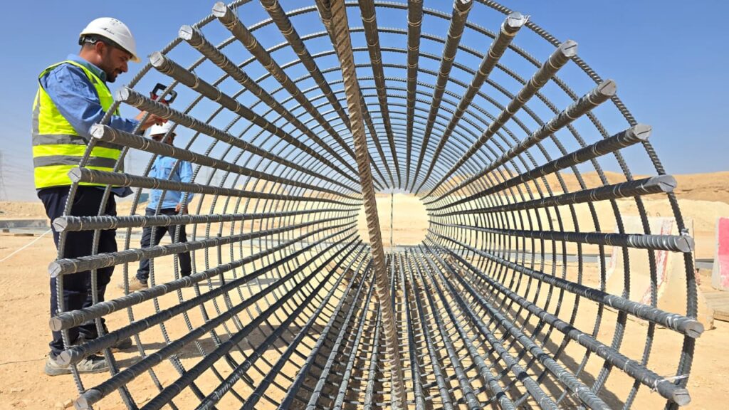
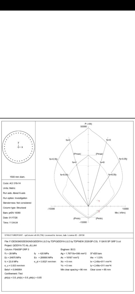
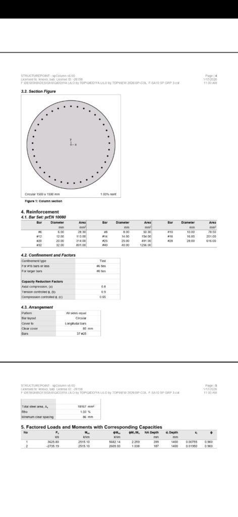
The shaft reinforcement consisted of:
- 37 longitudinal bars
- 25 mm diameter reinforcement
The shaft behaves as a heavily loaded structural member subjected simultaneously to:
- Compression
- Tension
- Bending
- Shear
Tie reinforcement was also provided for:
- Shear resistance
- Crack control
- Ductility improvement
- Prevention of bar buckling
Why This Foundation Design Is Conservative
Several conservative assumptions were incorporated into the design:
- Overload capacity factor of 1.5
- Reduced rock bond strength
- Consideration of poor RQD values
- Multiple safety factors
- Verification of all critical failure modes
This ensures high reliability under severe transmission line loading conditions.
Critical Failure Modes Prevented by the Design
The design successfully prevents:
Pull-Out Failure
Complete extraction of the shaft due to uplift forces.
Bearing Failure
Failure of the rock beneath the shaft base.
Lateral Failure
Excessive horizontal movement under wind loading.
Overturning Failure
Foundation rotation causing tower instability.
Structural Failure
Concrete crushing or reinforcement yielding.
Final Engineering Assessment
The designed pier foundation for the 380kV lattice steel tower Type F-SA10/SP represents a high-reliability foundation system developed using internationally accepted engineering principles.
The foundation dimensions:
- Shaft Diameter = 1.5 m
- Embedment Depth = 5.95 m
provide:
- Very high compression resistance
- Excellent uplift capacity
- Strong lateral stability
- Negligible settlement
- Safe overturning resistance
The design demonstrates advanced geotechnical and structural engineering integration suitable for severe transmission line loading conditions in mixed soil and rock formations.
Conclusion
The rock-socketed pier foundation designed for the 380kV lattice transmission tower successfully satisfies all critical engineering requirements related to:
- Compression resistance
- Uplift resistance
- Lateral stability
- Settlement control
- Structural integrity
Through conservative assumptions, advanced geotechnical analysis, and rigorous structural checks, the foundation ensures long-term reliability and operational safety for high-voltage transmission infrastructure.
For more transmission line engineering resources, design calculations, and foundation engineering insights, visit OHTL Design.

Eng. Mohamed Essam
Senior Civil Construction Engineer | Infrastructure & OHTL SpecialistNationality: Egyptian
LinkedIn Profile
Eng. Mohamed Essam is a Civil Engineer with over 10 years of experience in the execution and management of infrastructure projects, including substation works and high-voltage transmission lines (OHTL). He is currently leading the execution of a 380 kV Transmission Tower project within the Qiddiya Project in Riyadh, one of the Kingdom’s most prominent national initiatives.
Known for precision in field execution, strong coordination with technical teams, and a solid commitment to the highest standards of quality and safety.