
Introduction
Insulators are among the most important components of an overhead transmission line (OHTL). They provide electrical insulation between the energized conductor and the grounded transmission tower while also supporting the conductor mechanically.
For transmission lines operating in Saudi Arabia, one of the most important parameters in insulator selection is creepage distance.
Creepage distance becomes particularly important in areas exposed to salt, dust, sand, industrial pollution and moisture. Contaminants deposited on the surface of an insulator can create a partially conductive path. Under wet conditions, this path can allow leakage current to flow across the insulator surface and may eventually result in dry-band arcing or flashover.
Therefore, selecting an appropriate creepage distance is essential for maintaining reliable transmission-line operation.
This article explains the concept of creepage distance, how it is calculated, why coastal areas generally require higher values, and how engineers can apply the concept when designing transmission lines in Saudi Arabia.
What Is Creepage Distance?
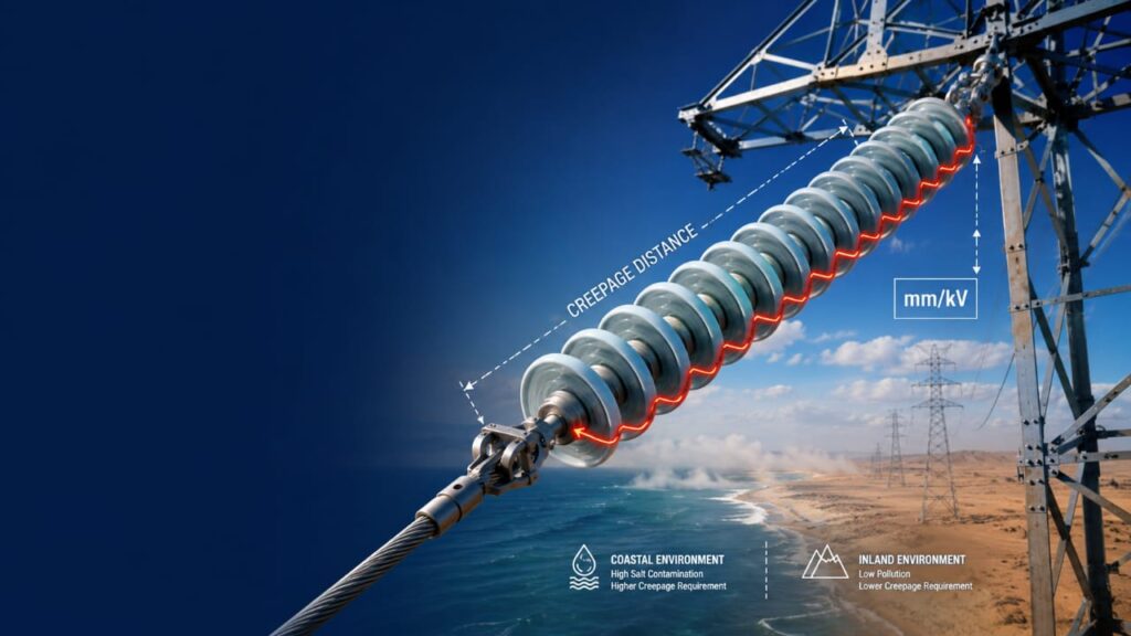
Creepage distance is the shortest distance measured along the surface of an insulating material between two conductive parts that are at different electrical potentials.
In a transmission-line insulator string, it represents the available leakage path along the surface of the insulator from the energized conductor side toward the grounded tower side.
It is important to understand that creepage distance is not the same as the straight-line or arcing distance through air.
In simple terms:
- Creepage distance → distance along the insulator surface.
- Clearance → shortest distance through air between conductive parts.
Both are important, but they address different insulation mechanisms.
Why Is Creepage Distance Important?
A clean insulator surface is normally highly insulating. However, transmission-line insulators are exposed to the surrounding environment throughout their service life.
Depending on the location, contaminants may include:
- Salt deposits
- Dust
- Sand
- Industrial pollutants
- Cement or construction dust
- Agricultural contaminants
- Moisture
- Condensation
When contaminants accumulate on an insulator and the surface becomes wet, the contamination layer can become partially conductive.
This creates a leakage-current path along the insulator surface.
If the leakage current becomes sufficiently high, localized dry areas can develop on the surface. These areas are known as dry bands. Electrical stress can then concentrate across these dry bands and produce dry-band arcing.
If the process becomes severe enough, the arc can extend across the insulation system and cause a flashover.
This is one of the main reasons why adequate creepage distance is required.
Creepage Distance vs. Clearance
These two terms are often confused during transmission-line design.
Creepage Distance
The distance measured along the surface of the insulator.
It is particularly important for:
- Pollution performance
- Salt contamination
- Surface leakage current
- Wet contamination conditions
Electrical Clearance
The shortest distance through air between energized and grounded components.
It is particularly important for:
- Lightning impulse withstand
- Switching impulse withstand
- Power-frequency insulation
- Insulator swing
- Tower geometry
- Conductor-to-tower clearances
A transmission-line design must satisfy both creepage distance and electrical clearance requirements.
Increasing creepage distance alone does not automatically solve a clearance problem.
Creepage Distance in mm/kV
For high-voltage transmission systems, creepage distance is commonly expressed as:
mm/kV
A simplified calculation is:
Required Creepage Distance = Creepage Distance Requirement × System Voltage
For example, if the applicable requirement is 50 mm/kV for a 230 kV system:
230 × 50 = 11,500 mm
Therefore:
Required creepage distance = 11.5 m
For a 380 kV system at the same 50 mm/kV level:
380 × 50 = 19,000 mm
Therefore:
Required creepage distance = 19.0 m
These calculations illustrate why the required creepage distance becomes substantial at higher transmission voltages.
Important: The applicable voltage basis and creepage requirement should always be confirmed from the governing project requirements. Values in mm/kV are not universal for every network or application.
Why Coastal Areas Require Higher Creepage Distance
Saudi Arabia has extensive coastal transmission infrastructure along the Red Sea and Arabian Gulf. Coastal environments create additional insulation challenges because of airborne salt.
Salt particles can settle on the surface of insulators. When the surface becomes wet due to humidity, condensation, fog or other moisture, the contamination layer can become conductive.
This increases the possibility of:
Contamination → Wet surface → Leakage current → Dry-band formation → Arcing → Flashover
For this reason, transmission lines located in coastal environments generally require a higher creepage distance than comparable lines in cleaner inland environments.
A higher creepage distance provides a longer surface leakage path and improves the insulator’s ability to withstand contamination.
Typical Creepage Distance Considerations in Saudi Arabia
In Saudi transmission-line design, environmental classification is an important factor when determining insulation requirements.
Typical design values encountered in Saudi applications include:
| Environment / Application | Typical Creepage Level |
|---|---|
| Coastal transmission lines | 50 mm/kV |
| Certain inland areas | 40 mm/kV |
| Lower-pollution inland applications in some operating regions | 31 mm/kV |
These values should be regarded as design reference levels rather than universal values. The final requirement depends on the applicable project specification, operating area, pollution conditions, equipment type and approved insulation design.
The key engineering principle is:
Higher environmental contamination generally requires a longer creepage distance.
Example: 380 kV Transmission Line
Consider a 380 kV transmission line located in a coastal environment where a design creepage level of 50 mm/kV is applicable.
The required creepage distance is:
380 × 50 = 19,000 mm
or:
19 metres
Now consider an inland application where 40 mm/kV is applicable:
380 × 40 = 15,200 mm
or:
15.2 metres
The difference is:
19,000 − 15,200 = 3,800 mm
Therefore, the coastal application requires approximately 3.8 metres more creepage distance under these assumed design values.
This demonstrates how environmental conditions can have a significant effect on the physical design of an insulator string.
Example: 230 kV Transmission Line
For a 230 kV transmission line:
At 50 mm/kV:
230 × 50 = 11,500 mm
Required creepage distance:
11.5 m
At 40 mm/kV:
230 × 40 = 9,200 mm
Required creepage distance:
9.2 m
Again, the required insulation surface distance changes significantly depending on the environmental classification.
How Is Creepage Distance Provided?
Creepage distance is achieved through the physical profile and arrangement of the insulator.
A simple smooth insulator would provide a relatively short surface path. Transmission-line insulators therefore use specially designed profiles containing features such as:
- Sheds
- Ribs
- Undersides
- Grooves
- Extended surface profiles
These features increase the distance that leakage current must travel along the surface.
The objective is to provide a sufficiently long and effective leakage path while maintaining good self-cleaning and pollution-performance characteristics.
Why Insulator Profile Matters
Two insulators can have similar overall physical dimensions but different creepage distances.
For example, an insulator with a more complex shed profile may provide a significantly longer leakage path without increasing its overall length by the same proportion.
This is why engineers should not determine insulation performance simply by measuring the physical length of an insulator.
The manufacturer’s certified creepage distance should be used when checking the insulation design.
Insulator Types Used in Transmission Lines
Several insulator technologies are used on overhead transmission lines, including:
Porcelain Insulators
Porcelain has been widely used in transmission systems for many decades. It provides good mechanical strength and established long-term performance.
Glass Insulators
Glass disc insulators are also widely used in some transmission applications. Their transparency and surface characteristics can be advantageous, although their suitability must be evaluated where vandalism or mechanical damage is a concern.
Long-Rod Insulators
Long-rod insulators provide a continuous insulating structure and can offer substantial creepage distance within a relatively streamlined arrangement.
Composite Insulators
Composite insulators typically consist of a fiberglass-reinforced core covered by a polymeric housing, commonly using silicone rubber.
They can offer advantages such as:
- Lightweight construction
- Good pollution performance
- Hydrophobic surface characteristics
- Easier handling
- Reduced structural loading
However, their long-term performance must be carefully considered for severe environmental conditions.
Creepage Distance for Porcelain and Glass Insulators
For porcelain and glass insulators, creepage distance is strongly influenced by:
- Insulator profile
- Number of units
- Unit diameter
- Shed configuration
- Pollution level
- Surface contamination
- Operating voltage
For a disc-insulator string, the approximate total creepage distance can be considered as the sum of the effective creepage distances of the individual units, subject to the manufacturer’s certified data and the applicable design methodology.
For example:
If one insulator unit provides approximately 400 mm of creepage distance and the string contains 30 units:
30 × 400 = 12,000 mm
The theoretical total is therefore approximately:
12 metres
However, engineers should use the actual manufacturer-certified creepage distance rather than relying on an assumed value.
Creepage Distance and Number of Insulator Units
A common misconception is:
“If one insulator has a higher creepage distance, we can always reduce the number of insulator units.”
This is not necessarily correct.
The number of units in a transmission-line insulator string is influenced by several factors, including:
- Required creepage distance
- Insulation coordination
- Power-frequency withstand
- Switching impulse withstand
- Lightning impulse withstand
- Mechanical strength
- String configuration
- Pollution performance
- Required electrical clearances
Therefore, increasing the creepage distance of an individual unit does not automatically mean that the total number of units can be reduced.
The complete insulation design must be checked.
Coastal Insulators and RTV Coating
In particularly exposed coastal environments, ceramic insulators may require additional surface protection.
One commonly used approach is RTV silicone rubber coating.
RTV stands for:
Room Temperature Vulcanizing
RTV silicone coating can improve the surface’s pollution performance by providing a hydrophobic surface and reducing the tendency for continuous conductive contamination films to develop.
It can be particularly useful for ceramic insulators installed in areas exposed to severe salt contamination.
However, RTV coating should be treated as part of the overall insulation strategy rather than as a substitute for proper creepage-distance design.
Composite Insulators and Creepage Distance
Composite insulators require a slightly different approach.
Silicone rubber surfaces can provide hydrophobic properties that help limit the formation of continuous conductive water films.
However, the designer must still consider:
- Total creepage distance
- Shed profile
- Pollution severity
- Hydrophobicity
- Dry-band arcing
- Corona
- End fittings
- Aging
- Environmental exposure
For high-voltage transmission lines, the design of corona rings and end fittings can also be important because excessive electric-field stress can contribute to aging and surface deterioration.
Creepage Distance in Coastal vs. Inland Design
A simplified comparison can help illustrate the design philosophy.
| Parameter | Coastal Environment | Inland Environment |
|---|---|---|
| Salt contamination | Higher | Generally lower |
| Pollution severity | Often higher | Depends on location |
| Required creepage | Generally higher | Generally lower |
| Insulator profile | Pollution-resistant profile may be required | Depends on pollution |
| RTV coating | May be required in specified zones | Usually location-dependent |
| Composite insulator assessment | Requires careful environmental evaluation | Depends on application |
| Maintenance consideration | Often more demanding | Site-dependent |
The important point is that geographical location alone does not tell the complete story. Actual pollution severity and environmental exposure should also be considered.
What Happens If Creepage Distance Is Too Low?
Insufficient creepage distance can result in:
1. Increased leakage current
Contamination and moisture can create a conductive path along the insulator surface.
2. Dry-band formation
Parts of the wet surface may dry due to localized heating caused by leakage current.
3. Dry-band arcing
Electrical arcs can develop across the dry sections.
4. Surface flashover
If the arcing develops sufficiently, the insulation may fail completely.
5. Transmission-line outage
A flashover can result in protection-system operation and interruption of power transmission.
For a transmission network, repeated pollution flashovers can have significant consequences for system reliability, maintenance and availability.
What Happens If Creepage Distance Is Excessive?
More creepage distance is not automatically better in every design.
An unnecessarily large insulator string can result in:
- Increased tower dimensions
- Increased mechanical loading
- Increased cost
- Greater wind exposure
- Larger insulator swing
- Increased hardware requirements
- More complex tower geometry
Therefore, the objective is not simply to maximize creepage distance.
The objective is to provide the appropriate insulation performance for the actual environmental and electrical conditions.
Creepage Distance and OHTL Tower Design
Insulator selection directly affects transmission-tower design.
A longer insulator string can influence:
- Cross-arm dimensions
- Conductor-to-tower clearance
- Conductor swing
- Phase-to-phase clearance
- Tower body dimensions
- Ground clearance
- Hardware arrangement
This means that insulator selection should be completed early enough in the OHTL design process to allow the tower geometry to be properly coordinated.
A change from one insulator type to another should therefore trigger a clearance review.
Practical Design Workflow for Creepage Distance
For an OHTL project in Saudi Arabia, an engineer can follow this general workflow:
Step 1 — Identify the system voltage
Determine whether the line is, for example:
- 69 kV
- 110 kV
- 115 kV
- 132 kV
- 230 kV
- 380 kV
Step 2 — Determine the environmental condition
Establish whether the line is located in:
- Coastal environment
- Inland environment
- Industrial pollution zone
- Desert/dusty environment
- Other special pollution conditions
Step 3 — Establish the applicable creepage requirement
Determine the project-specific creepage level in mm/kV.
Step 4 — Calculate the required creepage distance
Use:
Required Creepage Distance = Design Creepage Level × Applicable Voltage
Step 5 — Select the insulator type
Evaluate:
- Porcelain
- Glass
- Long rod
- Composite
Step 6 — Select the string configuration
Determine whether the application requires:
- Suspension string
- Tension string
- Jumper string
- Single string
- Double string
- Special arrangement
Step 7 — Verify mechanical strength
Check the required mechanical failing load and conductor loading.
Step 8 — Verify electrical clearances
Check:
- Phase-to-phase clearance
- Phase-to-earth clearance
- Conductor-to-tower clearance
- Conductor-to-ground clearance
- Insulator swing
Step 9 — Check corona and hardware
For high-voltage applications, verify the suitability of:
- Corona rings
- Grading rings
- End fittings
- Arcing horns, where applicable
Step 10 — Complete the final design review
Ensure that the selected insulation system satisfies the project’s electrical, mechanical, environmental and construction requirements.
A Simple Example for OHTL Designers
Suppose an engineer is designing a 230 kV transmission line in a coastal region and the applicable project requirement is 50 mm/kV.
Required creepage:
230 × 50 = 11,500 mm
Therefore, the selected insulator arrangement must provide at least:
11.5 m of effective creepage distance
The engineer then selects an appropriate insulator type and configuration.
But the design does not stop there.
The engineer must also verify:
- Mechanical failing load
- Electrical clearances
- Insulator swing
- Tower geometry
- Pollution performance
- Hardware arrangement
- Corona protection
- Applicable project requirements
This is the key difference between simply calculating creepage distance and actually designing a reliable transmission-line insulation system.
Key Points to Remember
When working on transmission-line insulator design, remember these fundamental principles:
- Creepage distance is measured along the insulator surface.
- Clearance is measured through air.
- Creepage distance is especially important for pollution and salt contamination.
- Coastal transmission lines generally require higher creepage than comparable inland lines.
- Creepage requirements are commonly expressed in mm/kV.
- The applicable voltage basis must be confirmed from the governing project requirements.
- The number of insulator units cannot be selected based on creepage alone.
- Mechanical strength and electrical insulation must both be checked.
- Insulator profile has a major influence on pollution performance.
- RTV coating can provide additional pollution protection for ceramic insulators in specified applications.
- Composite insulators require consideration of hydrophobicity, aging, corona and environmental performance.
- Changing the insulator string can affect tower geometry and conductor clearances.
Conclusion
Creepage distance is a fundamental consideration in the design and selection of overhead transmission-line insulators. Its primary purpose is to provide an adequate surface leakage path so that contamination, moisture and pollution do not cause unacceptable leakage current, dry-band arcing or flashover.
For transmission lines in Saudi Arabia, the distinction between coastal and inland environments is particularly important. Coastal areas exposed to salt contamination generally require a higher level of creepage performance than cleaner inland locations.
However, a reliable insulation design cannot be based on creepage distance alone. The engineer must consider the complete system, including system voltage, pollution severity, insulator type, insulator profile, mechanical strength, electrical clearances, corona control, tower geometry and environmental conditions.
The best OHTL design is therefore not the one with the longest insulator string—it is the one that provides the right insulation performance for the actual operating environment while maintaining electrical reliability, mechanical integrity and economical tower design.
Frequently Asked Questions
What is creepage distance in a transmission line insulator?
Creepage distance is the shortest distance measured along the surface of an insulator between conductive parts at different electrical potentials. It helps prevent surface flashover under contaminated and wet conditions.
Why is creepage distance higher in coastal areas?
Coastal areas are exposed to salt and moisture. Salt deposits can make an insulator surface conductive when wet, increasing leakage current and the risk of dry-band arcing and flashover. A longer creepage path improves pollution performance.
What is the difference between creepage distance and clearance?
Creepage distance is measured along the insulator surface, whereas clearance is the shortest distance through air between conductive parts. Both are essential in transmission-line insulation design.
How is creepage distance calculated?
A basic calculation is:
Required Creepage Distance = Creepage Level (mm/kV) × Applicable Voltage (kV)
The applicable voltage basis and creepage level must be confirmed from the project requirements.
Is 50 mm/kV always required for transmission lines in Saudi Arabia?
No. The required creepage level depends on the operating environment, pollution severity, voltage level, project requirements and applicable insulation design criteria. Values such as 50, 40 and 31 mm/kV are used for different applications, but the project-specific requirement should always be verified.
Can a higher-creepage insulator reduce the number of insulator units?
Not necessarily. The number of units is influenced by creepage, insulation coordination, mechanical strength, electrical clearances and other design requirements. A higher creepage value per unit does not automatically permit reducing the number of units.
Why is RTV coating used on transmission-line insulators?
RTV silicone coating can improve pollution performance by providing a hydrophobic surface and reducing the formation of continuous conductive contamination films. Its use depends on the environmental and project requirements.
About OHTL Design
At OHTL Design, the focus is on practical knowledge related to overhead transmission lines, tower design, sag and tension, insulator selection, electrical clearances, line routing and transmission-line engineering.
The goal is to make complex OHTL engineering concepts easier to understand for design engineers, site engineers, consultants, students and professionals working in the power-transmission industry.